| Is the ignition switch ON- | Subaru Select Monitor > INSPECTION | Turn the ignition switch to ON, and select «Tire pressure monitor» using the Subaru Select Monitor. |
2.CHECK BATTERY. Check the battery voltage. | Is the voltage 11 V or more- | Subaru Select Monitor > INSPECTION | Charge or replace the battery. |
3.CHECK BATTERY TERMINAL. Check the battery terminal. | Is there poor contact at battery terminal- | Repair or tighten the battery terminal. | Subaru Select Monitor > INSPECTION |
4.CHECK SUBARU SELECT MONITOR COMMUNICATION. 1) Turn the ignition switch to ON. 2) Using the Subaru Select Monitor, check whether communication to other systems can be executed normally. | Is the system name displayed on Subaru Select Monitor- | Subaru Select Monitor > INSPECTION | Subaru Select Monitor > INSPECTION |
5.CHECK SUBARU SELECT MONITOR COMMUNICATION. 1) Turn the ignition switch to OFF. 2) Disconnect the TPMS & keyless entry CM connector or TPMS CM connector. 3) Turn the ignition switch to ON. 4) Check whether communication to other systems can be executed normally. | Is the system name displayed on Subaru Select Monitor- | Replace the TPMS & keyless entry CM or TPMS CM. Tire Pressure Monitoring System | Subaru Select Monitor > INSPECTION |
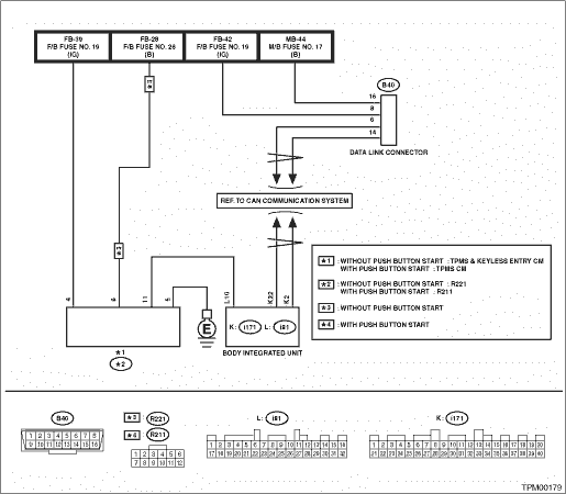
6.CHECK HARNESS CONNECTOR BETWEEN EACH CONTROL MODULE AND BODY INTEGRATED UNIT. 1) Turn the ignition switch to OFF. 2) Disconnect the connector of the TPMS & keyless entry CM or TPMS CM. 3) Measure the resistance between the body integrated unit and chassis ground. Connector & terminal (B40) No. 6 — Chassis ground: (B40) No. 14 — Chassis ground: | Is the resistance 1 M- or more- | Subaru Select Monitor > INSPECTION | Repair the harness and connector between each control module and body integrated unit. |
7.CHECK OUTPUT SIGNAL TO TPMS & KEYLESS ENTRY CM OR TPMS CM. 1) Turn the ignition switch to ON. 2) Measure the voltage between TPMS & keyless entry CM or TPMS CM and chassis ground. Connector & terminal (B40) No. 6 (+) — Chassis ground (−): (B40) No. 14 (+) — Chassis ground (−): | Is the voltage less than 1 V- | Subaru Select Monitor > INSPECTION | Repair the harness and connector between each control module and body integrated unit. |
8.CHECK HARNESS CONNECTOR BETWEEN TPMS & KEYLESS ENTRY CM OR TPMS CM AND BODY INTEGRATED UNIT. 1) Turn the ignition switch to OFF. 2) Measure the resistance between TPMS & keyless entry CM connector or TPMS CM connector and body integrated unit. Connector & terminal Without push button start (R221) No. 11 — (i81) No. 10: With push button start (R211) No. 11 — (i81) No. 10: | Is the resistance less than 0.5 -- | Subaru Select Monitor > INSPECTION | Repair the harness and connector between TPMS & keyless entry CM or TPMS CM and body integrated unit. |
9.CHECK TPMS & KEYLESS ENTRY CM CONNECTOR OR TPMS CM CONNECTOR. | Is the connector inserted into the TPMS & keyless entry CM or TPMS CM until it locks- | Subaru Select Monitor > INSPECTION | Insert the connector into the TPMS & keyless entry CM or TPMS CM. |
10.CHECK POWER SUPPLY CIRCUIT. 1) Turn the ignition switch to ON. 2) Measure the ignition power supply voltage between TPMS & keyless entry CM connector or TPMS CM connector and chassis ground. Connector & terminal Without push button start (R221) No. 4 (+) — Chassis ground (−): With push button start (R211) No. 4 (+) — Chassis ground (−): | Is the voltage 10 — 15 V- | Subaru Select Monitor > INSPECTION | Repair open circuit of the harness between TPMS & keyless entry CM or TPMS CM and battery. |
11.CHECK HARNESS CONNECTOR BETWEEN TPMS & KEYLESS ENTRY CM OR TPMS CM AND CHASSIS GROUND. 1) Turn the ignition switch to OFF. 2) Disconnect the connector from the TPMS & keyless entry CM or TPMS CM. 3) Measure the resistance of harness between TPMS & keyless entry CM or TPMS CM and chassis ground. Connector & terminal Without push button start (R221) No. 5 — Chassis ground: With push button start (R211) No. 5 — Chassis ground: | Is the resistance less than 0.5 -- | Subaru Select Monitor > INSPECTION | Repair open circuit of the harness of TPMS & keyless entry CM or TPMS CM. |
12.CHECK POOR CONTACT OF CONNECTOR. | Is there poor contact in TPMS & keyless entry CM power supply or TPMS CM power supply, ground line and body integrated unit- | | Replace the TPMS & keyless entry CM or TPMS CM. Tire Pressure Monitoring System |
 Operation
