Subaru Legacy BN/BS (2015-2019) Service Manual: Removal
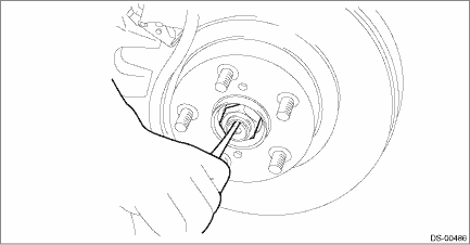
1. Lift up the vehicle, and then remove the front wheels. 2. Remove the nut - axle. CAUTION: Do not loosen the nut - axle while the front axle is loaded. Doing so may damage the hub unit COMPL. (1) Lift the crimped section of the nut - axle. (2) Remove the nut - axle using a socket wrench while depressing the brake pedal.
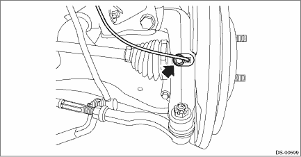
3. Remove the disc brake assembly. Front Disc Brake Assembly > REMOVAL 4. Remove the disc rotor. Front Disc Rotor > REMOVAL 5. Remove the bolts, and remove the front ABS wheel speed sensor.
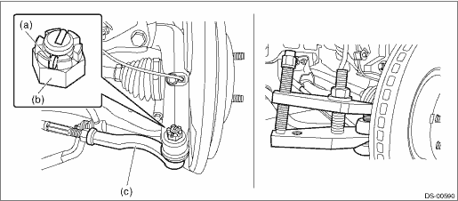
6. Disconnect the tie-rod end. (1) Pull out the cotter pin (a). (2) Remove the castle nut (b). (3) Using a tie-rod ball joint puller, remove the tie-rod end (c). CAUTION: Use a tool appropriate to the structure, and be careful not to damage the boot of the joint while removing. The boot may be damaged depending on the tool used. Preparation tool: Tie-rod ball joint puller
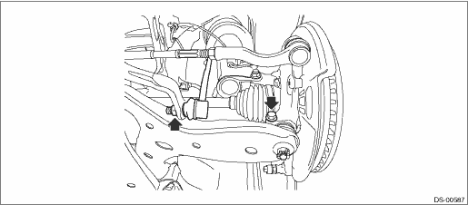
7. Remove the stabilizer link and ball joint.
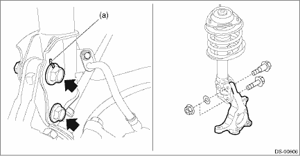
8. Remove the front drive shaft. Front Drive Shaft > REMOVAL 9. Remove the housing assembly - front axle. CAUTION: • Be careful of the weight of the housing assembly - front axle. • Be careful not to damage the spline portion of the drive shaft. (1) Place an alignment mark (a) on the adjusting bolt and the strut assembly. (2) Remove the adjusting bolts and flange bolts for the strut assembly, and then remove the housing assembly - front axle.
NOTE: While holding the adjusting bolt side, tighten the nut side. 10. For removal of the hub unit COMPL - front axle, refer to “Front Hub Unit Bearing”. Front Hub Unit Bearing > REMOVAL |
 Front axle
...
 Installation
1. Install the housing assembly - front axle to the strut assembly.(1) Align alignment marks on the camber adjusting bolt and strut.(2) While holding the bolt head of adjusting bolt, tighten the nut.T ...
Other materials:
Adjustment
1. NOZZLE - WINDSHIELD WASHER1. Turn the wiper switch to OFF position.2. While the vehicle is at a standstill, insert the washer nozzle adjustment tool (a) into upper side (b) and lower side (c) of the nozzle - windshield washer to perform necessary adjustment.CAUTION:Washer nozzle is made of resin. ...
