Subaru Legacy BN/BS (2015-2019) Service Manual: Adjustment
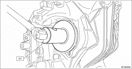
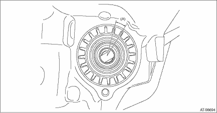
1. Using the ST, screw-in the retainer until resistance is felt. NOTE: RH side should be screwed-in more than LH side.
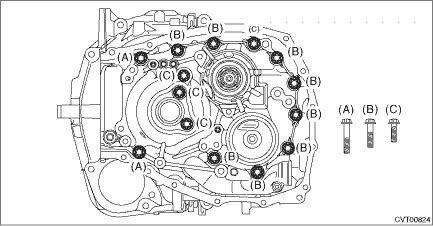
2. Remove the remaining liquid gasket from the mating surface completely. 3. Using the ST, install the drive pinion assembly to converter case.
NOTE: Do not confuse the three different-length bolts when installing. Tightening torque: 43 N·m (4.4 kgf-m, 31.7 ft-lb)
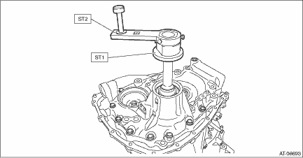
4. Rotate the drive pinion shaft ten times or more using ST1 and ST2.
5. While rotating the pinion shaft, tighten the retainer LH and loosen the retainer RH until the shaft can't be turned anymore. The backlash is “zero” when the pinion shaft comes to the point where it doesn't rotate. 6. After the “zero” state is established, loosen the retainer LH by 3 notches and secure it with the lock plate. Retighten the retainer RH until it stops. Rotate the drive pinion 2 or 3 times. Tighten the retainer RH further 1-3/4 notches. This sets the preload. Finally, secure the retainer with its lock plate.
NOTE: Turning the retainer by every one tooth changes the backlash approx. 0.05 mm (0.0020 in).
7. Insert the two SUBARU genuine axle shafts into differential case.
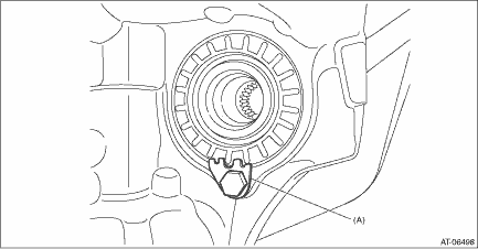
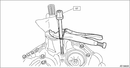
8. Install the ST to the drive pinion retainer, and wrap the drive pinion shaft with cloth and pinch with vise pliers. Using a tie-wrap or a wire, fix the vise pliers to the ST. Make sure the drive pinion shaft does not move.
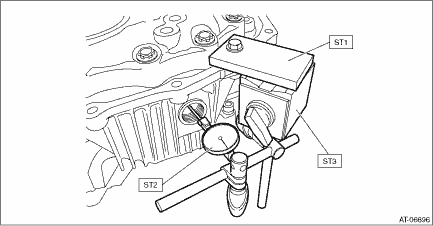
9. Check the backlash is within specification using ST1, ST2 and ST3.
Backlash: 0.13 — 0.18 mm (0.005 — 0.007 in)
10. Adjust the teeth contact of the front differential and drive shaft. Drive Pinion Shaft Assembly > ADJUSTMENT |
 Removal
1. Remove the transmission assembly. Automatic Transmission Assembly > REMOVAL2. Remove the air breather hose. Air Breather Hose > REMOVAL3. Remove the control valve body. Control Valve Body > REMO ...
 Installation
1. Install the front differential assembly to the converter case.NOTE:Be careful not to damage the inside of the case (especially the mounting surface of the differential side retainers).2. Install th ...
Other materials:
Assembly
1. CAM CARRIER RH1. Install the filter to the cam carrier RH.NOTE:Use a new filter.Filter insert position:Cam carrier RH end face 0+0 −0.5 mm (+0 −0.0197 in) position(A)0 — 0.5 mm (0 — 0.0197 in) 2. Set the intake camshaft RH and the exhaust camshaft RH to the cam carrier RH.NOTE: ...
