Subaru Legacy BN/BS (2015-2019) Service Manual: Adjustment
CAUTION: When the wheel alignment has been adjusted, perform the following adjustment. – Lane keep assist learning value clear (model with EyeSight): Clear Active Lane Keep System Learning Value > OPERATION – VDC sensor midpoint setting mode: VDC Control Module and Hydraulic Control Unit (VDCCM&H/U) > ADJUSTMENT 1. FRONT CAMBER 1. Adjust the camber angle to the following value.
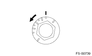
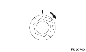
2. Loosen the two flange nuts while holding the strut bolts. 3. Turn the camber adjusting bolt so that the camber is set at specification. NOTE: Moving the adjusting bolt by one scale changes the camber by approximately 0°10'.
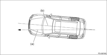
4. Tighten two new flange nuts. Tightening torque: 155 N·m (15.8 kgf-m, 114.3 ft-lb) NOTE: While holding the adjusting bolt side, tighten the nut side. 2. STEERING ANGLE 1. Adjust the steering angle of both inner and outer wheels. (1) Loosen the steering tie-rod lock nut (a), and rotate the tie-rod.
(2) Turn the tie-rod to adjust the steering angle of both inner and outer wheels. (3) Tighten the steering tie-rod lock nut (a). Tightening torque: 85 N·m (8.7 kgf-m, 62.7 ft-lb) NOTE: Check and correct the tie-rod boot if twisted. 2. Check the toe-in. Wheel Alignment > INSPECTION 3. FRONT WHEEL TOE-IN When adjusting the toe-in, adjust it to the following value. Wheel Alignment > ADJUSTMENT Toe-in: Adjustment value 0±2 mm (0.00±0.08 in) 1. Check that the left and right wheel steering angles are within specification. 2. Loosen the left and right side steering tie-rod lock nuts (a). 3. Turn the left and right tie-rods by equal amounts until the toe-in is at the specification. NOTE: Both the left and right tie-rods are right-hand threaded. To increase toe-in, turn both tie-rods clockwise by equal amount (viewing from the inside of vehicle). 4. Tighten the steering tie-rod lock nut (a).
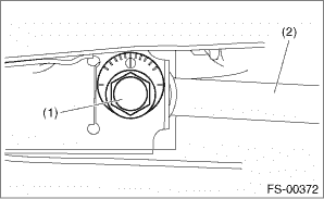
Tightening torque: 85 N·m (8.7 kgf-m, 62.7 ft-lb) 5. Check and correct the tie-rod boot if twisted. 4. REAR WHEEL TOE-IN When adjusting, adjust it to the following value. Toe-in: Adjustment value 3±2 mm (0.12±0.08 in) 1. Loosen the self-locking nut after holding the bolt head section of lateral link assembly - front. NOTE: When loosening or tightening the adjusting bolt, hold the bolt head and turn the self-locking nut.
2. Turn the adjusting bolt until toe-in is within the specification. NOTE: When the left and right wheels are adjusted for toe-in at the same time, the movement of one scale graduation changes toe-in by approx. 6.0 mm (0.24 in).
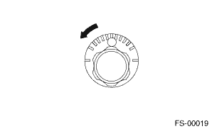
3. Attach and tighten a new self-locking nut. Tightening torque: 120 N·m (12.2 kgf-m, 88.5 ft-lb) 5. THRUST ANGLE When adjusting, adjust it to the following value. Thrust angle: Adjustment value 0°±20' Less than 20' when “L” is 15 mm (0.6 in) or less
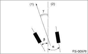
1. Make thrust angle adjustments by turning the toe-in adjusting bolts of the rear suspension equally in the same direction. 2. When one rear wheel is adjusted in a toe-in direction, adjust the other rear wheel equally in toe-out direction, in order to make the thrust angle adjustment. 3. When the left and right adjusting bolts are turned by one graduation, the thrust angle will change approx. 15'. (“L” is approx. 11 mm (0.43 in).) NOTE: Thrust angle is a mean value of left and right wheel toe angles in relation to the vehicle body center line. Vehicle is driven straight in the thrust angle direction while slanting in the oblique direction depending on the degree of the mean thrust angle.
Thrust angle: γ = (α − β)/2 α: Rear RH wheel toe-in angle β: Rear LH wheel toe-in angle Substitute only the positive toe-in values from each wheel into α and β in the calculation.
| |||||||||||||||||||||||||||||||||||||||||||||||||||||||||||||||||||


 Inspection
Check the following items before performing the wheel alignment measurement.• Tire inflation pressure• Uneven wear of RH and LH tires, or difference of sizes• Tire runout• Exce ...

Other materials:
Dtc p0328 knock/combustion vibration sensor 1 circuit high bank 1 or single sensor
DTC DETECTING CONDITION:Immediately at fault recognitionTROUBLE SYMPTOM:• Poor driving performance• Knocking occursCAUTION:After servicing or replacing faulty parts, perform Clear Memory Mode Clear Memory Mode > OPERATION, and Inspection Mode Inspection Mode > PROCEDURE.WIRING DIAGRAM: ...
