Subaru Legacy BN/BS (2015-2019) Service Manual: Assembly
1. Apply CVTF to the seal of reverse brake piston and install it to intermediate case.
2. Install the return spring.
3. Set the spring retainer and snap ring.
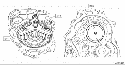
4. Set the ST1, ST2 and ST3 to intermediate case.
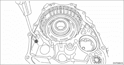
5. Compress the return spring using the ST attached, and install the snap ring.
6. Check the operation of reverse brake piston by blowing compressed air intermittently from intermediate case hole.
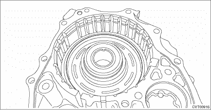
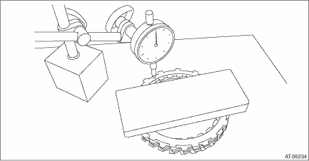
7. Place the dish plate, driven plate, drive plate and retaining plate neatly in this order on surface table. 8. Set the dial gauge to retaining plate, and read its scale. NOTE: The value, which is read in the gauge at this time, is zero point. 9. Scale and record the weight “Z” of a flat board which will be put on retaining plate. NOTE: • Use a stiff board which does not bend against load as a flat board to be put on retaining plate. • Use a flat board weighing less than 84 N (8.6 kgf, 18.9 lb). 10. Put the flat board on retaining plate.
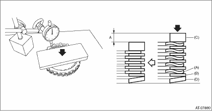
11. Using the following formula, read the push/pull gauge and calculate “N”. N = 84 N (8.6 kgf, 18.9 lb) – Z 84 N (8.6 kgf, 18.9 lb) : Load applied to clutch plate Z: Flat board weight 12. Press the center of retaining plate by applying a force of “N” or more using push/pull gauge, and then measure and record the compression amount “A”. NOTE: Measure at four points with a 90° interval and calculate the average.
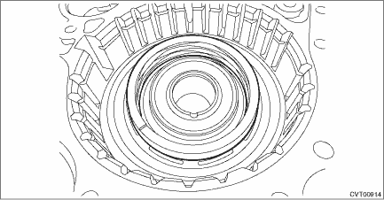
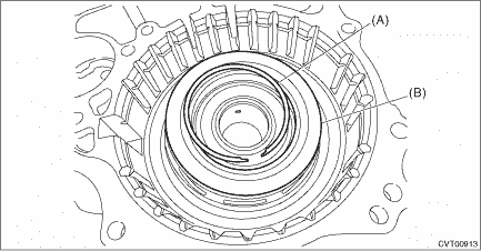
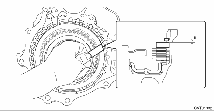
13. Install the dish plate, drive plate, driven plate, retaining plate and snap ring to intermediate case. NOTE: Install the dish plate in the correct direction. 14. Measure and record the clearance “B” between the retaining plate and snap ring.
15. Piston stroke calculation Calculate with A and B dimensions recorded before. If it exceeds the limit, replace with a new drive plate and adjust within the initial standard value. S mm (in) = A + B S: Piston stroke A: Compression amount of drive plate and dish plate B: Clearance between retaining plate and snap ring Initial standard: 2.88 — 3.18 mm (0.113 — 0.125 in) Limit thickness: 3.38 mm (0.133 in)
| ||||||||||||||||||||||||||||||

 Removal
NOTE:For removal of reverse brake assembly, refer to “Intermediate Case”. Intermediate Case > REMOVAL ...
 Installation
NOTE:For installation of reverse brake assembly, refer to “Intermediate Case”. Intermediate Case > INSTALLATION ...
Other materials:
Dtc p2021 tgv position sensor/switch circuit low bank 2
DTC DETECTING CONDITION:Immediately at fault recognitionTROUBLE SYMPTOM:• Improper idling• Engine stalls.• Poor driving performanceCAUTION:After servicing or replacing faulty parts, perform Clear Memory Mode Clear Memory Mode > OPERATION, and Inspection Mode Inspection Mode > PRO ...
