Subaru Legacy BN/BS (2015-2019) Service Manual: Assembly
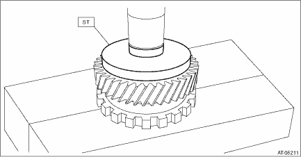
1. Using the ST, install the parking gear to transfer reduction drive gear.
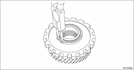
2. Install the snap ring to transfer reduction drive gear.
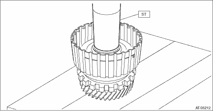
3. Using the ST, install the transfer reduction drive gear to transfer reduction drive gear shaft.
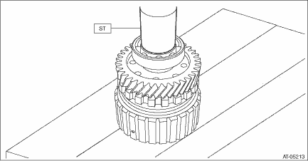
4. Using the ST, install the ball bearing. NOTE: Use a new ball bearing.
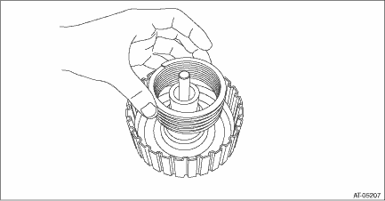
5. Attach the transfer clutch piston to the reduction drive gear shaft. NOTE: Apply CVTF to the transfer clutch piston lip. 6. Install the return spring.
7. Install the transfer clutch piston seal. 8. Using the ST, install the snap ring.
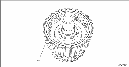
9. Install the pressure plate, driven plate, drive plate and snap ring.
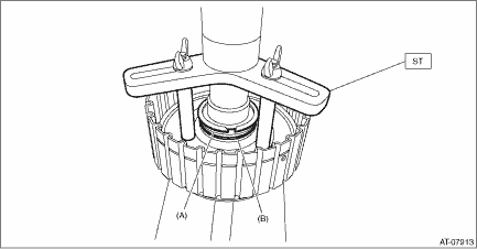
10. Before measuring clearance “A”, place same thickness shims on both sides to prevent the retaining plate from tilting. 11. When clearance “A” exceeds the limit for use, replace the drive plate and driven plate as a set, and select and adjust the pressure plate within the initial specified value. Initial standard: 0.7 — 1.1 mm (0.028 — 0.043 in) Limit thickness: 1.6 mm (0.063 in)
12. Check the clearance between the snap ring and retaining plate. Transfer Clutch > INSPECTION | ||||||||||||||||||||||

 Disassembly
1. Remove the snap ring, and then remove the retaining plate, drive plate and driven plate.(A)Snap ring2. Using the ST, remove the snap ring.ST 18762AA001COMPRESSOR SPECIAL TOOL(A)Snap ring(B)Trans ...

Other materials:
Installation
1. SEAT BELT OUTER - REAR RH & LH (SEDAN MODEL)CAUTION:If the hook - rear seat is disconnected from the vehicle body, make sure to replace the hook - rear seat with a new part to prevent the decline of the fixed force of the seat.1. Before installation, perform a unit inspection of retractor. Rear ...
