Subaru Legacy BN/BS (2015-2019) Service Manual: Assembly
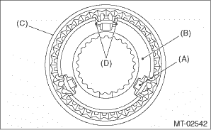
NOTE: • Match the alignment marks, and install the coupling sleeve and then install the shifting insert. • Make sure that there is no large clearance at both sides of the shifting insert after assembly.
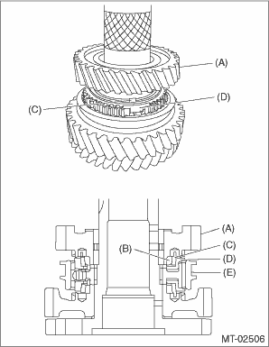
1. Install the 1st driven gear, 1st inner baulk ring, 1st synchro cone, 1st outer baulk ring and 1st-2nd synchronizer hub. NOTE: • Install the 1st-2nd synchronizer hub in proper direction. • Align the protrusion of the 1st outer baulk ring into the groove of the 1st-2nd synchronizer hub.
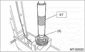
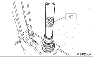
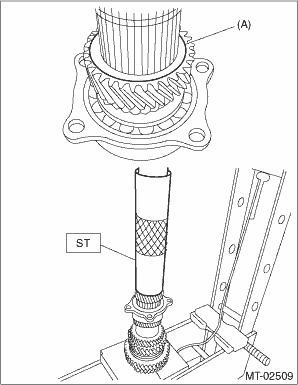
2. Install the 2nd driven gear bushing using ST and a press. CAUTION: Do not apply a load in excess of 10 kN (1 ton, 1.1 US ton, 1.0 Imp ton). NOTE: • Attach a cloth to the end of the driven shaft to prevent damage. • When press fitting, align the oil holes of the driven shaft and 2nd driven gear bushing.
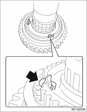
3. Install the 1st-2nd coupling sleeve. NOTE: • Install the 1st-2nd coupling sleeve in proper direction. • Align the alignment marks of 1st-2nd coupling sleeve and the 1st-2nd synchronizer hub.
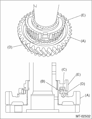
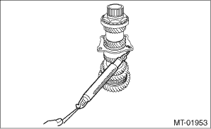
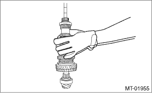
4. Install the 1st-2nd shifting insert. NOTE: Press in the ball part to install.
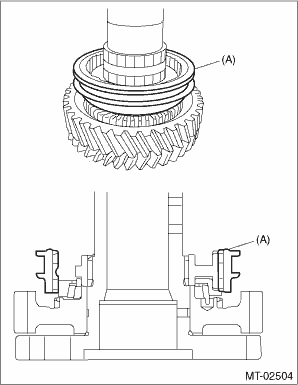
5. Install the 2nd outer baulk ring, 2nd synchro cone, 2nd inner baulk ring and 2nd driven gear.
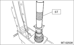
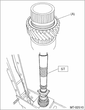
6. Install the key to the driven shaft. 7. Using the ST and a press, install the 3rd-4th driven gear. CAUTION: Do not apply a load in excess of 10 kN (1 ton, 1.1 US ton, 1.0 Imp ton). NOTE: • Match the groove on the 3rd-4th driven gear to the key. • Install the 3rd-4th driven gear in the proper direction.
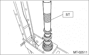
8. Using the ST and a press, install the double ball bearing. CAUTION: Do not apply a load in excess of 10 kN (1 ton, 1.1 US ton, 1.0 Imp ton). NOTE: Use a new double ball bearing.
9. Install the 5th driven gear using ST and press. CAUTION: Do not apply a load in excess of 10 kN (1 ton, 1.1 US ton, 1.0 Imp ton). NOTE: Install the 5th driven gear with the groove side facing the 6th driven gear.
10. Install the drive pinion spacer to the driven shaft. 11. Install the 6th driven gear using ST and press. CAUTION: Do not apply a load in excess of 10 kN (1 ton, 1.1 US ton, 1.0 Imp ton). NOTE: Install with the stepped side on the end surface of the 6th driven gear facing the rear ball bearing side.
12. Using the ST and a press, install the ball bearing. CAUTION: Do not apply a load in excess of 10 kN (1 ton, 1.1 US ton, 1.0 Imp ton).
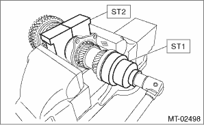
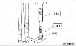
13. Install the lock nut using ST1 and ST2. NOTE: Use a new lock nut. Tightening torque: 440 N·m (44.9 kgf-m, 324.5 ft-lb)
14. Using a spring scale, check that the initial load of the ball bearings is 0.1 to 1.5 N (0.01 to 0.15 kgf, 0.02 to 0.34 lbf).
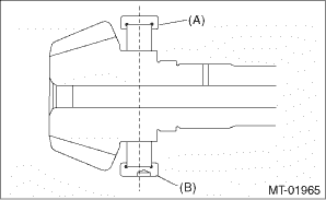
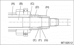
15. Crimp the lock nut at two locations so that the dimension (B) becomes 39.1 mm (1.54 in) or less. CAUTION: When crimping the lock nut, be careful not to crack it.
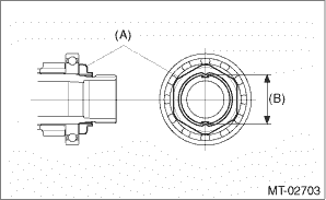
16. Install the roller bearing. NOTE: • Use a new roller bearing. • Install with the knock pin hole of the roller bearing outer race facing the rear side.
17. Install the washer using ST1, ST2 and a press. CAUTION: Do not apply a load in excess of 10 kN (1 ton, 1.1 US ton, 1.0 Imp ton).
18. Install the thrust bearing and needle bearing and install the driven shaft assembly.
19. Install the drive pinion collar, needle bearing, adjusting washer No. 2, thrust bearing, adjusting washer No. 1 and differential bevel gear sleeve in this order.
20. Adjust the thrust bearing preload. Drive Pinion Shaft Assembly > ADJUSTMENT |
 Disassembly
NOTE:• Attach a cloth to the end of driven shaft (on the frictional side of the thrust needle bearing) to prevent damage during disassembly or reassembly.• When replacing the coupling slee ...

Other materials:
System operation
CAUTION
Do not touch the SRS airbag system
components with bare hands right
after deployment. Doing so can
cause burns because the components
can be very hot as a result of
deployment.
The SRS airbags can function only when
the ignition switch is in the "ON" position. ...
