Subaru Legacy BN/BS (2015-2019) Service Manual: Disassembly
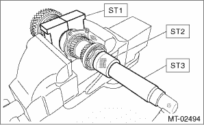
NOTE: • Attach a cloth to the end of driven shaft (on the frictional side of the thrust needle bearing) to prevent damage during disassembly or reassembly. • When replacing the coupling sleeve and synchronizer hub, replace them as a set. Because these must engage at the specified point, avoid disassembly as much as possible. If it is necessary to disassemble, mark the engaging points on the splines beforehand. 1. Flatten the tab of the lock nut. 2. Remove the lock nut using ST1, ST2 and ST3.
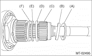
3. Remove the lock washer, washer, differential bevel gear sleeve, adjusting washer No. 1, thrust bearing and adjusting washer No. 2.
4. Draw out the drive pinion shaft from driven shaft. 5. Remove the needle bearing and drive pinion collar.
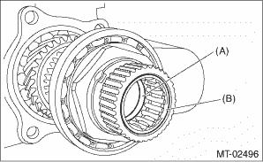
6. Remove the needle bearing and thrust bearing.
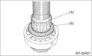
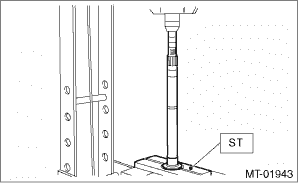
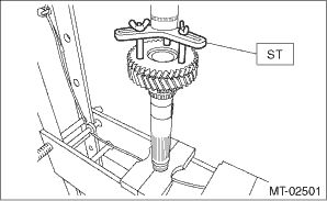
7. Remove the roller bearing and washer using ST and a press.
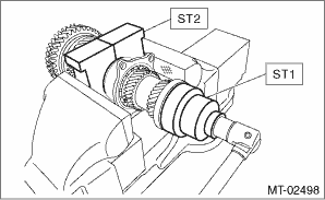
8. Flatten the tab of the lock nut. 9. Remove the lock nut using ST1 and ST2.
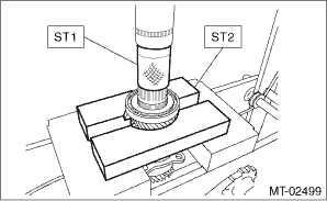
10. Remove the ball bearing, 6th driven gear and drive pinion spacer using the ST1, ST2 and a press.
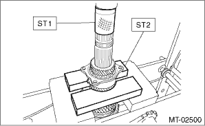
11. Remove the 5th driven gear, double ball bearing and 3rd-4th driven gear using ST1, ST2 and a press.
12. Remove the key. 13. Remove the 2nd driven gear, 2nd inner baulk ring, 2nd synchro cone, 2nd outer baulk ring, 1st-2nd shifting insert and 1st-2nd coupling sleeve. CAUTION: When removing 1st-2nd coupling sleeve, be careful not to lose the 1st-2nd shifting insert. 14. Remove the 1st driven gear, 1st inner baulk ring, 1st synchro cone, 1st outer baulk ring, 2nd driven gear bushing and 1st-2nd synchronizer hub using ST and a press.
|
 Inspection
Disassembled parts should be washed with cleaning solvent first, then inspected carefully.1. BearingReplace the bearings in the following cases.• When the bearing balls, outer races and inner ra ...
 Assembly
NOTE:• Match the alignment marks, and install the coupling sleeve and then install the shifting insert.• Make sure that there is no large clearance at both sides of the shifting insert aft ...
Other materials:
