Subaru Legacy BN/BS (2015-2019) Service Manual: Blind spot detection rear cross traffic alert
NoteFor procedure of each component in the Subaru Rear Vehicle Detection system, refer to the respective sections. • Radar sensor: Radar Sensor • BSD/RCTA OFF switch: Switches and Harness • Combination meter: Combination Meter • Outer mirror assembly: Outer Mirror Assembly General descriptionPreparation tool1. SPECIAL TOOL
2. GENERAL TOOL
Caution• Before disconnecting connectors of sensors or units, be sure to disconnect the ground cable from battery. When replacing the electrical parts provided with memory functions that store contents specified by a customer, record the memory contents before disconnecting the battery ground cable. • For precautions for rear vehicle detection function, refer to “CAUTION” in “Blind Spot Detection/Rear Cross Traffic Alert (DIAGNOSTICS)” section. General Description > CAUTION LocationRefer to “LOCATION” of “Blind Spot Detection/Rear Cross Traffic Alert (DIAGNOSTICS)” section. Electrical Component Location > LOCATION Component1. RADAR SENSOR
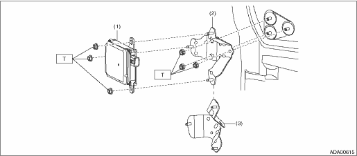
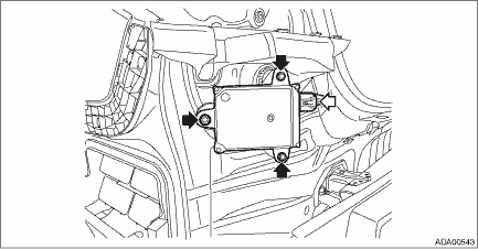
Radar sensorRemoval1. RADAR SENSOR LH (MASTER) 1. Disconnect the ground terminal from battery sensor. NOTE 2. Remove the bumper face - rear. Rear Bumper > REMOVAL 3. Remove the radar sensor LH (master). (1) Disconnect the connector. (2) Remove the nut and remove the radar sensor LH.
4. Remove the radar bracket. (1) Remove the harness clamp. (OUTBACK model) (2) Remove the nut and remove the radar bracket.
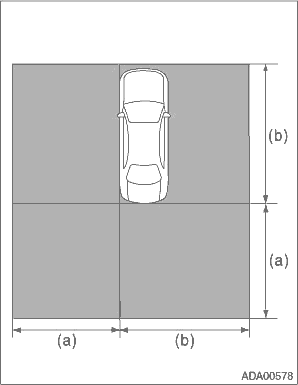
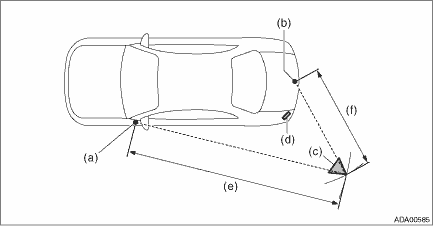
2. RADAR SENSOR RH (SLAVE) NOTE: For the procedure of radar sensor RH (slave), refer to “RADAR SENSOR LH (MASTER)”. Adjustment1. RADAR AXIS ADJUSTMENT CAUTION: • After removal/installation or replacement of the radar sensor, perform the radar axis adjustment. • The procedure for the master is only shown here. However the procedure for the slave can also be done in the same way as the master. 1. Before performing the inspection, check the following items. • The inflation pressure of tires is correct. • The vehicle does not have load. • Vehicle’s fuel tank is fully filled. 2. Place the vehicle on a level surface, where approximately 5 square meters (16.41 square ft) area can be secured behind the vehicle. CAUTION: • No metallic objects around the vehicle and on the floor in the area. • Do not let in objects other than the radar reflector (ST), persons and metallic objects inside the area. NOTE: The illustration shows the secured area for adjusting the radar axis on the master side.
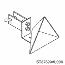
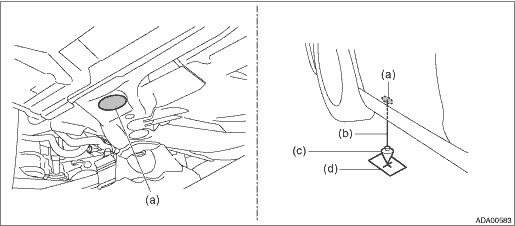
3. Prepare the Subaru Select Monitor, measure, leveling line, plumb bob, packing tape, RADAR REFLECTOR (ST), and stand or tripod for fixing the RADAR REFLECTOR. Preparation tool: ST: RADAR REFLECTOR (87699AL00A) 4. Set up the radar reflector. NOTE: The following procedure explains the method of setting the radar reflector so that the distance between radar reflector and radar sensor is 1,500 mm (4.92 ft) and the radar is positioned at an angle of 50 degree. (1) Suspend the plumb bob from the center of the front hole cap, and mark the position where the plumb bob touches the ground. (Point A)
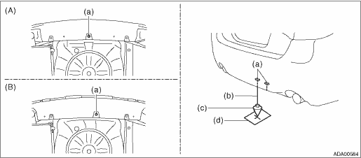
NOTE: Stick the packing tape etc. on the floor, then make a marking on the tape. (2) Suspend the plumb bob from the center of the center clip located on the lower side of the rear bumper, and mark the position where the plumb bob touches the ground. (Point B)
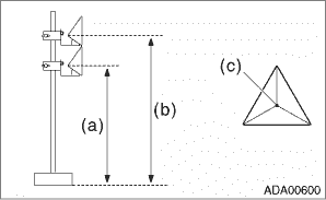
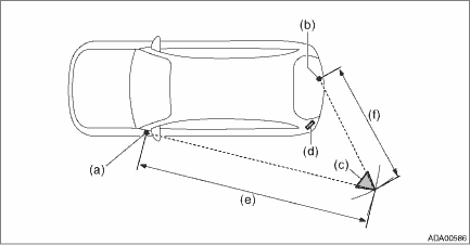
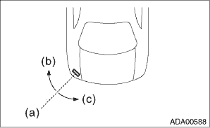
NOTE: Stick the packing tape etc. on the floor, then make a marking on the tape. (3) Stretch a leveling line to draw an arc with the marked point A as a pivot. (4) Stretch a leveling line to draw an arc with the marked point B as a pivot. (5) Set up the radar reflector at the cross point. CAUTION: When setting up the radar reflector, adjust the height so that the center of the pyramid points at the radar sensor as shown in the figure.
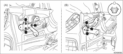
• Sedan model
• OUTBACK model
5. Connect the Subaru Select Monitor. NOTE: Use the Subaru Select Monitor equipped with the latest version of the software. 6. Turn the ignition switch to ON and wait for 10 seconds. 7. Perform radar axis adjustment. (1) Connect the Subaru Select Monitor. (2) On «Start» display, select «Diagnosis». (3) On «Vehicle selection» display, enter vehicle information and select «Confirmed». (4) On «Main Menu» display, select «Each System». (5) On «Select System» display, select «RADAR ASSY B&S LH» or «RADAR ASSY B&S RH». (6) On «Select Function» display, select «Work Support». (7) From the work support item list, select «RADAR Alignment». (8) Follow the messages displayed on the Subaru Select Monitor screen when working. NOTE: Deviation of radar axis direction is indicated by + (plus) or − (minus).
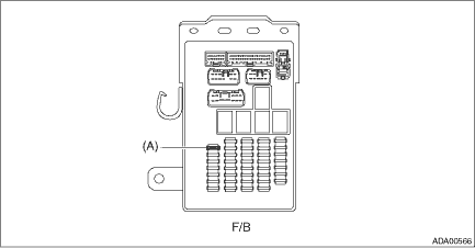
(9) If the result is out of permissive range, it is assumed that the radar reflector position may be incorrect or the radar bracket or its installation location on the vehicle may be deformed. Check the set position of the radar reflector, radar bracket and other attachment, and perform the radar axis adjustment again. Installation1. Install the radar bracket. Tightening torque: 7.5 N·m (0.8 kgf-m, 5.5 ft-lb) 2. Install the radar sensor. Tightening torque: 7.5 N·m (0.8 kgf-m, 5.5 ft-lb) 3. Install the bumper face - rear. 4. Connect the ground terminal to battery sensor. NOTE 5. Perform the adjustment of the radar sensor radar axis. Radar Sensor > ADJUSTMENT Relay and fuseLocation
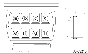
NOTE: For other related fuses, refer to the wiring diagram. Power Supply Circuit Inspection1. CHECK FUSE 1. Remove the fuse and inspect visually. 2. If the fuse is blown out, replace the fuse. NOTE: If the fuse is blown again, check the system wiring harness. Switches and harnessRemovalBSD/RCTA OFF switch 1. Disconnect the ground terminal from battery sensor. NOTE 2. Remove the cover assembly - instrument panel LWR driver. Instrument Panel Lower Cover > REMOVAL 3. Release the claws and remove the BSD/RCTA OFF switch (f).
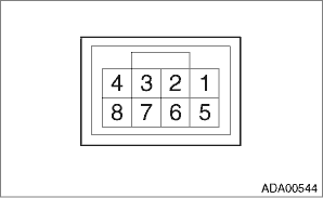
InspectionBSD/RCTA OFF switch 1. Measure the resistance between connector terminals. Preparation tool: Circuit tester
2. Apply battery voltage between the connector terminals to check lighting condition of illumination inside the switch.
3. Replace the BSD/RCTA OFF switch if the inspection result is not within the standard value. InstallationBSD/RCTA OFF switch 1. Install the BSD/RCTA OFF switch. 2. Install the cover assembly - instrument panel LWR driver. 3. Connect the ground terminal to battery sensor. NOTE | |||||||||||||||||||||||||||||||||||||||||||||||||||||||||||||||||||||||||||||||||||||||||||||||||||||||||||||||||||||||||||||||||||||||

 Inspection
Refer to “Basic Diagnostic Procedure” of “Blind Spot Detection/Rear Cross Traffic Alert (DIAGNOSTICS)” section. Basic Diagnostic Procedure ...

Other materials:
Installation
CAUTION:• Be sure to use a new flange nut and self-locking nut.• Always tighten the bushing in the state where the vehicle is at curb weight and the wheels are in full contact with the ground.1. Install the nut of shock mount - rear.Tightening torque:30 N·m (3.1 kgf-m, 22.1 ft-lb) ...
