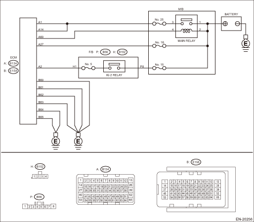
1.CHECK MAIN RELAY. 1) Turn the ignition switch to OFF. 2) Remove the main relay. 3) Connect the battery to main relay terminals No. 1 and No. 2. 4) Measure the resistance between main relay terminals. | Is the resistance less than 1 -- | Diagnostics for Engine Starting Failure > CHECK POWER SUPPLY AND GROUND LINE OF ENGINE CONTROL MODULE (ECM) | Replace the main relay. Main Relay |
2.CHECK GROUND CIRCUIT FOR ECM. 1) Disconnect the connector from ECM. 2) Measure the resistance of harness between ECM connector and chassis ground. Connector & terminal (B158) No. 60 — Chassis ground: (B158) No. 61 — Chassis ground: (B158) No. 62 — Chassis ground: (B158) No. 63 — Chassis ground: (B158) No. 64 — Chassis ground: (B158) No. 65 — Chassis ground: | Is the resistance less than 5 -- | Diagnostics for Engine Starting Failure > CHECK POWER SUPPLY AND GROUND LINE OF ENGINE CONTROL MODULE (ECM) | Repair the open circuit of harness between ECM connector and engine ground terminal. |
3.CHECK INPUT VOLTAGE OF ECM. 1) Turn the ignition switch to ON. 2) Measure the voltage between ECM connector and chassis ground. Connector & terminal (B134) No. 2 (+) — Chassis ground (−): (B134) No. 27 (+) — Chassis ground (−): | Is the voltage 10 V or more- | Diagnostics for Engine Starting Failure > CHECK POWER SUPPLY AND GROUND LINE OF ENGINE CONTROL MODULE (ECM) | Repair the open or ground short in the harness of power supply circuit. |
4.CHECK INPUT VOLTAGE OF MAIN RELAY. Measure the voltage between main relay connector and chassis ground. Connector & terminal No. 1 (+) — Chassis ground (−): No. 2 (+) — Chassis ground (−): | Is the voltage 10 V or more- | Diagnostics for Engine Starting Failure > CHECK POWER SUPPLY AND GROUND LINE OF ENGINE CONTROL MODULE (ECM) | Repair the open or ground short in the harness of power supply circuit. |
5.CHECK INPUT VOLTAGE OF ECM. 1) Turn the ignition switch to OFF. 2) Install the main relay. 3) Turn the ignition switch to ON. 4) Measure the voltage between ECM connector and chassis ground. Connector & terminal (B134) No. 60 (+) — Chassis ground (−): | Is the voltage 10 V or more- | Diagnostics for Engine Starting Failure > CHECK POWER SUPPLY AND GROUND LINE OF ENGINE CONTROL MODULE (ECM) | Repair the open circuit of harness between ECM connector and main relay connector. |
6.CHECK INPUT VOLTAGE OF ECM. 1) Turn the ignition switch to OFF. 2) Connect the connector to ECM. 3) Turn the ignition switch to ON. 4) Measure the voltage between ECM connector and chassis ground. Connector & terminal (B134) No. 1 (+) — Chassis ground (−): (B134) No. 14 (+) — Chassis ground (−): | Is the voltage 10 V or more- | Check ignition control system. Diagnostics for Engine Starting Failure > IGNITION CONTROL SYSTEM | Repair the harness and connector. NOTE: In this case, repair the following item: • Open circuit in harness between ECM connector and main relay connector • Poor contact of main relay connector • Poor contact of ECM connector |
 Fuel injector circuit
 Fuel pump circuit