1.CHECK FUSE. 1) Remove the ignition key from ignition switch. Or, turn off the power. | | Diagnostics Chart for Security Indicator Light > INSPECTION | Replace the fuse. If the replaced fuse blows out easily, repair the short circuit in the harness between the fuse and body integrated unit. |
2.CONFIRM DESTINATION. Verify the destination of the vehicle. | Is destination for C0 or C5- | Diagnostics Chart for Security Indicator Light > INSPECTION | Diagnostics Chart for Security Indicator Light > INSPECTION |
3.CHECK IMMOBILIZER CM. Check the current data «Ignition SW input» of immobilizer CM. Read Current Data | Does the display change in accordance with the ignition switch OFF ←> ON- | Diagnostics Chart for Security Indicator Light > INSPECTION | Diagnostics Chart for Security Indicator Light > INSPECTION |
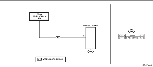
4.CHECK IGNITION SWITCH CIRCUIT. 1) Turn the ignition switch to OFF. 2) Remove the F/B fuse No. 3. 3) Measure the voltage between F/B fuse No. 3 (lower stream side) and chassis ground. Connector & terminal F/B fuse No. 3 (lower stream side) (+) — Chassis ground (−): | Is the voltage 6 V or more- | Repair the short circuit to power supply in harness between the immobilizer CM and fuse. | Diagnostics Chart for Security Indicator Light > INSPECTION |
5.CHECK IGNITION SWITCH CIRCUIT. Check the current data «Ignition SW input» of immobilizer CM. Read Current Data | | Replace the immobilizer CM. Immobilizer Control Module | Diagnostics Chart for Security Indicator Light > INSPECTION |
6.CHECK IGNITION SWITCH CIRCUIT. 1) Disconnect the connector from immobilizer CM. 2) Measure the resistance between immobilizer CM connector terminal and fuse. Connector & terminal (i34) No. 2 — F/B fuse No. 3 (lower stream side): | Is the resistance less than 10 -- | Replace the immobilizer CM. Immobilizer Control Module | Replace the open circuit of harness between the immobilizer CM and fuse. |
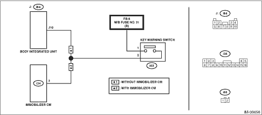
7.CHECK IMMOBILIZER CM. Check the current data «key-lock warning SW» of immobilizer CM. Read Current Data | Does the display change in accordance with the ignition key removal/insertion- | Diagnostics Chart for Security Indicator Light > INSPECTION | Check the key switch circuit. Diagnostics Chart for Security Indicator Light > INSPECTION |
8.CHECK IMMOBILIZER CM. 1) Check the current data «Immobilizer indicator output» of immobilizer CM. Read Current Data 2) Remove the ignition key from ignition switch. 3) Wait at least 60 seconds. | | Diagnostics Chart for Security Indicator Light > INSPECTION | Replace the immobilizer CM. Immobilizer Control Module |
9.CHECK SECURITY INDICATOR LIGHT. 1) Disconnect the connector from body integrated unit. 2) Connect the resistor (100 -) between the body integrated unit connector terminal (i171) No. 26 and chassis ground. | Does the security indicator light illuminate- | Diagnostics Chart for Security Indicator Light > INSPECTION | Diagnostics Chart for Security Indicator Light > INSPECTION |
10.CHECK BODY INTEGRATED UNIT GROUND CIRCUIT. Measure the resistance between the body integrated unit connector terminal and chassis ground. Connector & terminal (B280) No. 2 — Chassis ground: (i84) No. 4 — Chassis ground: | Is the resistance less than 10 -- | Diagnostics Chart for Security Indicator Light > INSPECTION | Repair the open circuit of the body integrated unit ground circuit. |
11.CHECK BODY INTEGRATED UNIT POWER SUPPLY CIRCUIT. Measure the voltage between the body integrated unit connector terminal and chassis ground. Connector & terminal (B280) No. 4 (+) — Chassis ground (−): (B280) No. 7 (+) — Chassis ground (−): (B281) No. 32 (+) — Chassis ground (−): | Is the voltage 10 V or more- | Replace the body integrated unit. Body Integrated Unit | Check the harness for open or short circuit between body integrated unit and fuse. |
12.CHECK COMBINATION METER CIRCUIT. 1) Remove the combination meter. Combination Meter 2) Measure the voltage between combination meter connector terminal and chassis ground. Connector & terminal (i10) No. 1 (+) — Chassis ground (−): | Is the voltage 1 V or more- | Diagnostics Chart for Security Indicator Light > INSPECTION | Check for an open or short circuit in the harness between the combination meter and fuse. |
13.CHECK COMBINATION METER CIRCUIT. Measure the resistance between the body integrated unit connector terminal and combination meter connector terminal. Connector & terminal (i171) No. 26 — (i10) No. 19: | Is the resistance less than 10 -- | LED bulb is defective. Replace the combination meter case assembly. Combination Meter > DISASSEMBLY | Repair the harness or connector. |
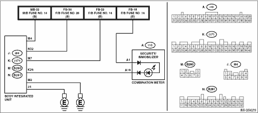
 Clear memory mode operation
 Electrical component location location