Subaru Legacy BN/BS (2015-2019) Service Manual: Disassembly
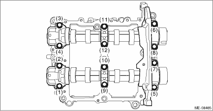
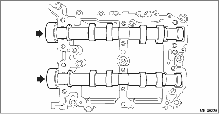
1. CAM CARRIER RH 1. Loosen the bolts (front camshaft cap RH, intake center camshaft cap RH, intake rear camshaft cap RH, exhaust center camshaft cap RH, and exhaust rear camshaft cap RH) equally, a little at a time in numerical sequence as shown in the figure, and remove each camshaft cap. NOTE: Arrange camshaft caps in order so that they can be installed in their original positions.
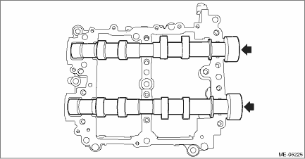
2. Remove the intake camshaft RH and the exhaust camshaft RH from cam carrier RH.
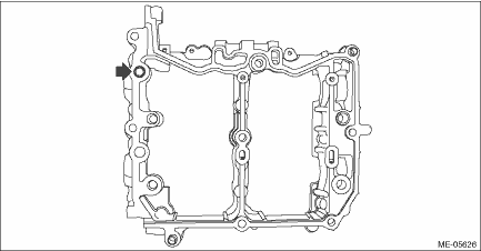
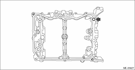
3. Remove the filter from cam carrier RH.
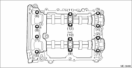
4. Remove the liquid gasket from cam carrier RH and front camshaft cap RH, intake rear camshaft cap RH and exhaust rear camshaft cap RH. 2. CAM CARRIER LH 1. Loosen the bolts (front camshaft cap LH, intake center camshaft cap LH, intake rear camshaft cap LH, exhaust center camshaft cap LH and exhaust rear camshaft cap LH) equally, a little at a time in numerical sequence as shown in the figure, and remove each camshaft cap. NOTE: Arrange camshaft caps in order so that they can be installed in their original positions.
2. Remove the intake camshaft LH and the exhaust camshaft LH from cam carrier LH.
3. Remove the filter from cam carrier LH.
4. Remove the liquid gasket from cam carrier LH and front camshaft cap LH, intake rear camshaft cap LH and exhaust rear camshaft cap LH. |
 Inspection
1. Visually check the cam carrier filter, and if clogging is found, replace with a new part.2. Check the camshaft journals for damage and wear. Replace the camshaft if faulty.3. Check the cam face con ...
 Cam clearance
...
Other materials:
To install the front cover
CAUTION
When reclining the rear seatback,
move the front cover backward so
that the cover is not damaged.
Align the right side of the front cover
with the triangle mark before fixing the
cover in place.
Push the front cover to the right side
and shorten the ...
