Honda Civic manuals

Subaru Legacy BN/BS (2015-2019) Service Manual: Dtc b1013 ignition power

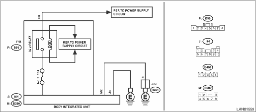
DTC DETECTING CONDITION:

Voltage failure caused by poor contact of IGN power supply circuits

IGN voltage was outside the range of 8.3 — 16.7 V, when the IGN power supply was ON.

Time Needed for Diagnosis:

40 s or more

TROUBLE SYMPTOM:

Symptoms such as shift lock or wiper not operating may occur.

WIRING DIAGRAM:

Shift lock control system Shift Lock Control System > WIRING DIAGRAM

STEPCHECKYESNO

1.CHECK DTC.

Read the DTC of body integrated unit using Subaru Select Monitor. Read Diagnostic Trouble Code (DTC)

Is DTC B1013 displayed- (Current malfunction)

Diagnostic Procedure with Diagnostic Trouble Code (DTC) > DTC B1013 IGNITION POWER

Diagnostic Procedure with Diagnostic Trouble Code (DTC) > DTC B1013 IGNITION POWER

2.CHECK DTC.

1) Turn the ignition switch to OFF.

2) Disconnect and then connect the body integrated unit connector.

3) Wait approx. 2 minutes.

4) Turn the ignition switch to ON.

5) Read the DTC of body integrated unit using Subaru Select Monitor. Read Diagnostic Trouble Code (DTC)

Is DTC B1013 displayed- (Current malfunction)

Diagnostic Procedure with Diagnostic Trouble Code (DTC) > DTC B1013 IGNITION POWER

Diagnostic Procedure with Diagnostic Trouble Code (DTC) > DTC B1013 IGNITION POWER

3.CHECK FUSE.

1) Turn the ignition switch to OFF.

2) Check the fuse.

Is the fuse OK-

Diagnostic Procedure with Diagnostic Trouble Code (DTC) > DTC B1013 IGNITION POWER

Replace the defective fuse.

4.CHECK HARNESS.

1) Turn the ignition switch to ON.

2) Using the tester, measure the voltage between terminals.

Connector & terminal

F/B fuse No. 5 (+) — Chassis ground (−):

Is the voltage 8.5 — 16.5 V-

Replace the body integrated unit. Body Integrated Unit

Diagnostic Procedure with Diagnostic Trouble Code (DTC) > DTC B1013 IGNITION POWER

5.CHECK IG2 RELAY.

Perform individual inspection of IG2 relay. Relay and Fuse

Is there any fault-

Replace the relay.

Repair the harness between F/B and M/B.

6.CHECK CONNECTOR.

1) Turn the ignition switch to OFF.

2) Disconnect the body integrated unit connector.

Is there poor contact of connector-

Repair or replace the poor contact of connector.

Even if DTC is displayed, the circuit has returned to a normal condition at this time. Reproduce the failure, and then perform the diagnosis again.

NOTE:

In this case, temporary poor contact of connector, temporary open or short circuit of harness may be the cause.

Dtc b1014 acc power
DTC DETECTING CONDITION:Voltage failure caused by poor contact of ACC power supply circuitACC voltage was outside the range of 8.3 — 16.7 V, when ACC power supply was ON.Time Needed for Diagnosis:40 ...

Dtc b1012 battery backup power supply
DTC DETECTING CONDITION:Voltage failure caused by poor contact of battery power supply backup circuitsBAT (back-up) voltage was outside the range of 8.3 — 16.7 V, when the BAT (back-up) power supply ...

Other materials:

Dtc b2300 rear radar circuit low
DTC DETECTING CONDITION:• Short circuit to ground in the harness between radar sensor and outer mirror assembly• Ground short circuit of the harness in outer mirror assembly module (Malfunction of the outer mirror assembly)• Defective radar sensorTROUBLE SYMPTOM:• All functio ...

© 2017-2024 Copyright www.sulegacy.com