Honda Civic manuals

Subaru Legacy BN/BS (2015-2019) Service Manual: Dtc b1014 acc power

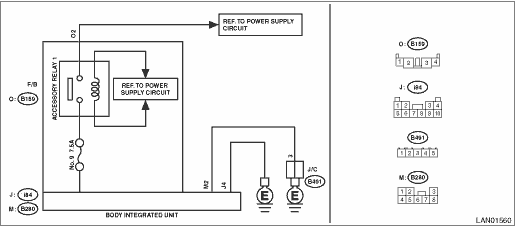
DTC DETECTING CONDITION:

Voltage failure caused by poor contact of ACC power supply circuit

ACC voltage was outside the range of 8.3 — 16.7 V, when ACC power supply was ON.

Time Needed for Diagnosis:

40 s or more

TROUBLE SYMPTOM:

DRL may not illuminate.

WIRING DIAGRAM:

Shift lock control system Shift Lock Control System > WIRING DIAGRAM

STEPCHECKYESNO

1.CHECK DTC.

Read the DTC of body integrated unit using Subaru Select Monitor. Read Diagnostic Trouble Code (DTC)

Is DTC B1014 displayed- (Current malfunction)

Diagnostic Procedure with Diagnostic Trouble Code (DTC) > DTC B1014 ACC POWER

Diagnostic Procedure with Diagnostic Trouble Code (DTC) > DTC B1014 ACC POWER

2.CHECK DTC.

1) Turn the ignition switch to OFF.

2) Disconnect and then connect the body integrated unit connector.

3) Wait approx. 2 minutes.

4) Turn the ignition switch to ON.

5) Read the DTC of body integrated unit using Subaru Select Monitor. Read Diagnostic Trouble Code (DTC)

Is DTC B1014 displayed- (Current malfunction)

Diagnostic Procedure with Diagnostic Trouble Code (DTC) > DTC B1014 ACC POWER

Diagnostic Procedure with Diagnostic Trouble Code (DTC) > DTC B1014 ACC POWER

3.CHECK FUSE.

1) Turn the ignition switch to OFF.

2) Check the fuse.

Is the fuse OK-

Diagnostic Procedure with Diagnostic Trouble Code (DTC) > DTC B1014 ACC POWER

Replace the defective fuse.

4.CHECK HARNESS.

1) Turn the ignition switch to ACC.

2) Using the tester, measure the voltage between terminals.

Connector & terminal

F/B fuse No. 9 (+) — Chassis ground (−):

Is the voltage 8.5 — 16.5 V-

Replace the body integrated unit. Body Integrated Unit

Diagnostic Procedure with Diagnostic Trouble Code (DTC) > DTC B1014 ACC POWER

5.CHECK ACCESSORY 1 RELAY.

Perform individual inspection of the accessory 1 relay. Relay and Fuse

Is there any fault-

Replace the relay.

Repair the harness between F/B and M/B.

6.CHECK CONNECTOR.

1) Turn the ignition switch to OFF.

2) Disconnect the body integrated unit connector.

Is there poor contact of connector-

Repair or replace the poor contact of connector.

Even if DTC is displayed, the circuit has returned to a normal condition at this time. Reproduce the failure, and then perform the diagnosis again.

NOTE:

In this case, temporary poor contact of connector, temporary open or short circuit of harness may be the cause.

Dtc b1015 key interlock circuit
DTC DETECTING CONDITION:Short to ground in key interlock circuitKey interlock output monitor is OFF, while BAT power supply voltage is 8.3 V or more and key lock operation judgment condition is met.Ti ...

Dtc b1013 ignition power
DTC DETECTING CONDITION:Voltage failure caused by poor contact of IGN power supply circuitsIGN voltage was outside the range of 8.3 — 16.7 V, when the IGN power supply was ON.Time Needed for Diagnos ...

Other materials:

List
DTCItemNoteU0073CAN FAILURE, BUS ‘OFF’ DETECTION Diagnostic Procedure with Diagnostic Trouble Code (DTC) > DTC U0073 CONTROL MODULE COMMUNICATION BUS OFFU0074CONTROL MODULE COMMUNICATION BUS "BODY-CAN" OFF Diagnostic Procedure with Diagnostic Trouble Code (DTC) > DTC U0074 CONTROL MODULE ...

© 2017-2024 Copyright www.sulegacy.com