Subaru Legacy BN/BS (2015-2019) Service Manual: Dtc p0030 a/f / o2 heater control circuit bank 1 sensor 1
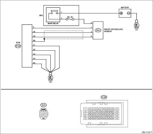
DTC DETECTING CONDITION: Detected when two consecutive driving cycles with fault occur. CAUTION: After servicing or replacing faulty parts, perform Clear Memory Mode Clear Memory Mode > OPERATION, and Inspection Mode Inspection Mode > PROCEDURE. WIRING DIAGRAM: • Engine Electrical System ENGINE TYPE FB (WITHOUT PUSH BUTTON START) Engine Electrical System > WIRING DIAGRAM • Engine Electrical System ENGINE TYPE FB (WITH PUSH BUTTON START) Engine Electrical System > WIRING DIAGRAM
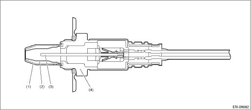
1. OUTLINE OF DIAGNOSIS Detect functional errors of the front oxygen (A/F) sensor heater. Judge as NG when it is determined that the front oxygen (A/F) sensor impedance is large when looking at engine status such as deceleration fuel cut. 2. COMPONENT DESCRIPTION
3. EXECUTION CONDITION
4. GENERAL DRIVING CYCLE Perform the diagnosis continuously when 20000 ms have elapsed since the fuel cut was initiated after starting the heater control. 5. DIAGNOSTIC METHOD If the duration of time while the following conditions are met is longer than the time indicated, judge as NG.
Time Needed for Diagnosis: 10000 ms Malfunction Indicator Light Illumination: Illuminates when malfunction occurs in 2 continuous driving cycles. |
 Dtc p0031 a/f / o2 heater control circuit low bank 1 sensor 1
DTC DETECTING CONDITION:Immediately at fault recognitionCAUTION:After servicing or replacing faulty parts, perform Clear Memory Mode Clear Memory Mode > OPERATION, and Inspection Mode Inspection Mod ...
 Dtc p0021 "a" camshaft position - timing over-advanced or system performance bank 2
DTC DETECTING CONDITION:Detected when two consecutive driving cycles with fault occur.TROUBLE SYMPTOM:• Engine stalls.• Improper idlingCAUTION:After servicing or replacing faulty parts, pe ...
Other materials:
Inspection
1. ACTUATOR LINK1. Visually check the operating range of the link, and remove the foreign matter if any.2. Operate the mode change switch, and check that the link operates normally.3. If it does not operate normally as the result of inspection, perform a unit inspection of motor - actuator mode.2. C ...
