Subaru Legacy BN/BS (2015-2019) Service Manual: Dtc p0102 mass or volume air flow sensor "a" circuit low
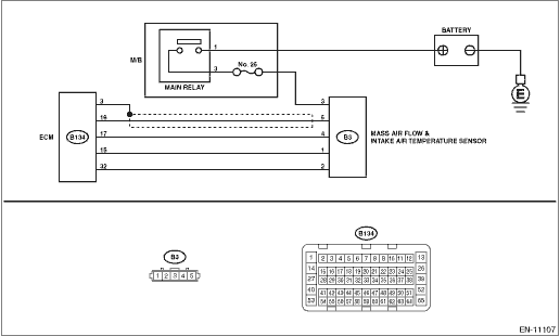
DTC DETECTING CONDITION: Immediately at fault recognition TROUBLE SYMPTOM: • Improper idling • Engine stalls. • Poor driving performance CAUTION: After servicing or replacing faulty parts, perform Clear Memory Mode Clear Memory Mode > OPERATION, and Inspection Mode Inspection Mode > PROCEDURE. WIRING DIAGRAM: • Engine Electrical System ENGINE TYPE EZ (WITHOUT PUSH BUTTON START) Engine Electrical System > WIRING DIAGRAM • Engine Electrical System ENGINE TYPE EZ (WITH PUSH BUTTON START) Engine Electrical System > WIRING DIAGRAM
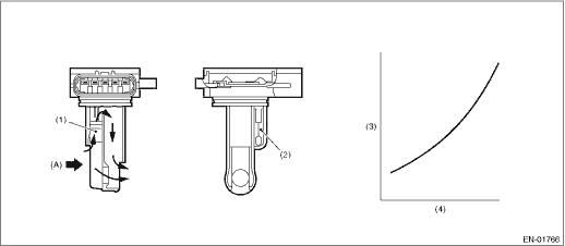
1. OUTLINE OF DIAGNOSIS Detect open or short circuits of the air flow sensor. Judge as NG if out of specification. 2. COMPONENT DESCRIPTION
3. EXECUTION CONDITION
4. GENERAL DRIVING CYCLE Always perform the diagnosis continuously. 5. DIAGNOSTIC METHOD If the duration of time while the following conditions are met is longer than the time indicated, judge as NG.
Time Needed for Diagnosis: 500 ms Malfunction Indicator Light Illumination: Illuminates as soon as a malfunction occurs. |
 Dtc p0103 mass or volume air flow sensor "a" circuit high
DTC DETECTING CONDITION:Immediately at fault recognitionTROUBLE SYMPTOM:• Improper idling• Engine stalls.• Poor driving performanceCAUTION:After servicing or replacing faulty parts, ...
 Dtc p0101 mass or volume air flow sensor "a" circuit range/performance
DTC DETECTING CONDITION:Detected when two consecutive driving cycles with fault occur.TROUBLE SYMPTOM:• Improper idling• Engine stalls.• Poor driving performanceCAUTION:After servici ...
Other materials:
Monitor (if equipped)
To clean the audio/navigation monitor,
wipe it with a silicone cloth or with a soft
cloth. If the monitor is extremely dirty,
clean it with a soft cloth moistened with
neutral detergent then carefully wipe off
any remaining detergent.
CAUTION
Do not spray neutral detergent
...
