Subaru Legacy BN/BS (2015-2019) Service Manual: Dtc p0112 intake air temperature sensor 1 circuit low bank 1
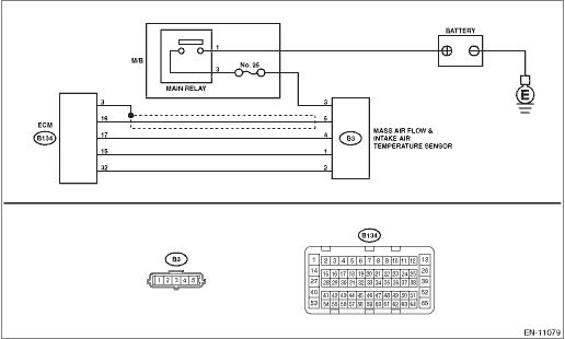
DTC DETECTING CONDITION: Immediately at fault recognition TROUBLE SYMPTOM: • Improper idling • Poor driving performance CAUTION: After servicing or replacing faulty parts, perform Clear Memory Mode Clear Memory Mode > OPERATION, and Inspection Mode Inspection Mode > PROCEDURE. WIRING DIAGRAM: • Engine Electrical System ENGINE TYPE FB (WITHOUT PUSH BUTTON START) Engine Electrical System > WIRING DIAGRAM • Engine Electrical System ENGINE TYPE FB (WITH PUSH BUTTON START) Engine Electrical System > WIRING DIAGRAM
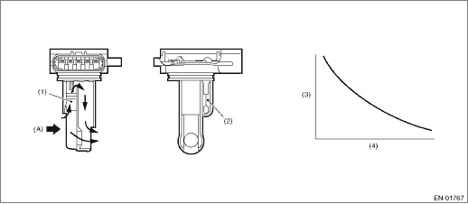
1. OUTLINE OF DIAGNOSIS Detect open or short circuit of the intake air temperature sensor. Judge as NG if out of specification. 2. COMPONENT DESCRIPTION
3. EXECUTION CONDITION
4. GENERAL DRIVING CYCLE Always perform the diagnosis continuously. 5. DIAGNOSTIC METHOD If the duration of time while the following conditions are met is longer than the time indicated, judge as NG.
Time Needed for Diagnosis: 500 ms Malfunction Indicator Light Illumination: Illuminates as soon as a malfunction occurs. |
 Dtc p0113 intake air temperature sensor 1 circuit high bank 1
DTC DETECTING CONDITION:Immediately at fault recognitionTROUBLE SYMPTOM:• Improper idling• Poor driving performanceCAUTION:After servicing or replacing faulty parts, perform Clear Memory M ...
 Dtc p0111 intake air temperature sensor 1 circuit range/performance bank 1
DTC DETECTING CONDITION:Detected when two consecutive driving cycles with fault occur.TROUBLE SYMPTOM:• Improper idling• Poor driving performanceCAUTION:After servicing or replacing faulty ...
Other materials:
Dtc b16a3 short in front sub sensor rh (to +b)
DIAGNOSIS START CONDITION:Ignition voltage is 10 V to 16 V.DTC DETECTING CONDITION:Shorted between front sub sensor RH circuit and power supply circuitWIRING DIAGRAM:NOTE:For the coupling connector, refer to “WIRING SYSTEM”.Airbag system Airbag System > WIRING DIAGRAMSTEPCHECKYESNO1.CHE ...
