
Subaru Legacy BN/BS (2015-2019) Service Manual: Dtc p0151 a/f / o2 sensor circuit low voltage bank 2 sensor 1
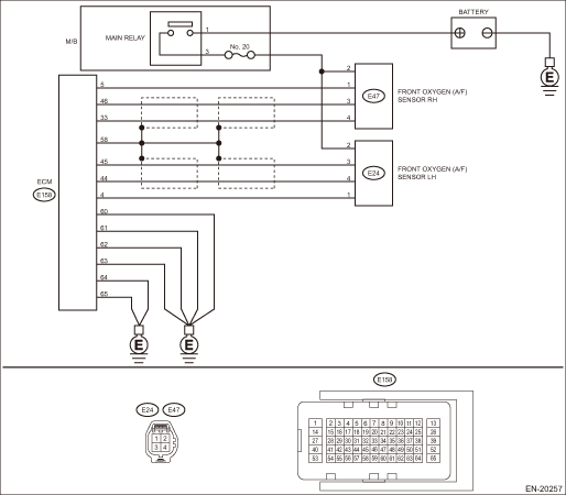
DTC DETECTING CONDITION: Immediately at fault recognition CAUTION: After servicing or replacing faulty parts, perform Clear Memory Mode Clear Memory Mode > OPERATION, and Inspection Mode Inspection Mode > PROCEDURE. WIRING DIAGRAM: • Engine Electrical System ENGINE TYPE EZ (WITHOUT PUSH BUTTON START) Engine Electrical System > WIRING DIAGRAM • Engine Electrical System ENGINE TYPE EZ (WITH PUSH BUTTON START) Engine Electrical System > WIRING DIAGRAM
1. OUTLINE OF DIAGNOSIS NOTE: For the detection standard, refer to DTC P0131. Diagnostic Procedure with Diagnostic Trouble Code (DTC) > DTC P0131 A/F / O2 SENSOR CIRCUIT LOW VOLTAGE BANK 1 SENSOR 1 |
 Dtc p0152 a/f / o2 sensor circuit high voltage bank 2 sensor 1
DTC DETECTING CONDITION:Immediately at fault recognitionCAUTION:After servicing or replacing faulty parts, perform Clear Memory Mode Clear Memory Mode > OPERATION, and Inspection Mode Inspection Mod ...
 Dtc p014f a/f / o2 sensor slow response - lean to rich bank 2 sensor 1
NOTE:For the diagnostic procedure, refer to DTC P014E. Diagnostic Procedure with Diagnostic Trouble Code (DTC) > DTC P014E A/F / O2 SENSOR SLOW RESPONSE - RICH TO LEAN BANK 2 SENSOR 11. OUTLINE OF DI ...
Other materials:
Dtc c2551 power supply relay
DTC DETECTING CONDITION:• When contact deposit malfunction of power supply relay is detected at initial check.• When power supply voltage failure is detected after the ignition switch is ON.• When power supply voltage drop is detected with 500 rpm engine speed reception.TROUBLE SYM ...
