Subaru Legacy BN/BS (2015-2019) Service Manual: Dtc p0335 crankshaft position sensor "a" circuit
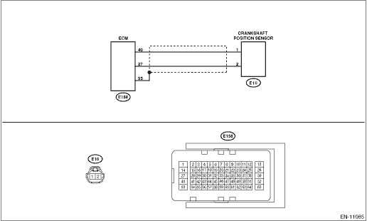
DTC DETECTING CONDITION: Immediately at fault recognition TROUBLE SYMPTOM: • Engine stalls. • Failure of engine to start CAUTION: After servicing or replacing faulty parts, perform Clear Memory Mode Clear Memory Mode > OPERATION, and Inspection Mode Inspection Mode > PROCEDURE. WIRING DIAGRAM: • Engine Electrical System ENGINE TYPE FB (WITHOUT PUSH BUTTON START) Engine Electrical System > WIRING DIAGRAM • Engine Electrical System ENGINE TYPE FB (WITH PUSH BUTTON START) Engine Electrical System > WIRING DIAGRAM
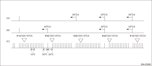
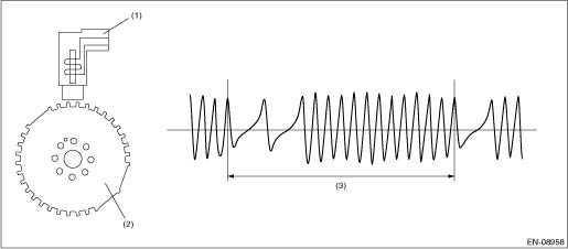
1. OUTLINE OF DIAGNOSIS Detect the open or short circuit of the crankshaft position sensor. Judge as NG when the crank signal is not input even though the starter was rotated. 2. COMPONENT DESCRIPTION
3. EXECUTION CONDITION
4. GENERAL DRIVING CYCLE Always perform the diagnosis continuously. 5. DIAGNOSTIC METHOD If the duration of time while the following conditions are met is longer than the time indicated, judge as NG.
Time Needed for Diagnosis: 3000 ms Malfunction Indicator Light Illumination: Illuminates as soon as a malfunction occurs. |
 Dtc p0336 crankshaft position sensor "a" circuit range/performance
DTC DETECTING CONDITION:Detected when two consecutive driving cycles with fault occur.TROUBLE SYMPTOM:• Engine stalls.• Failure of engine to startCAUTION:After servicing or replacing fault ...
 Dtc p0328 knock/combustion vibration sensor 1 circuit high bank 1 or single sensor
DTC DETECTING CONDITION:Immediately at fault recognitionTROUBLE SYMPTOM:• Poor driving performance• Knocking occursCAUTION:After servicing or replacing faulty parts, perform Clear Memory M ...
Other materials:
Installation
1. Attach the ST to converter case.ST 498277200STOPPER SET2. Replace the front differential side retainer oil seal. Differential Side Retainer Oil Seal > REPLACEMENTNOTE:• Be sure to replace the differential side retainer oil seal with a new part whenever the front drive shaft is removed f ...
