Subaru Legacy BN/BS (2015-2019) Service Manual: Installation
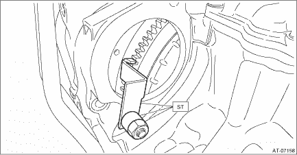
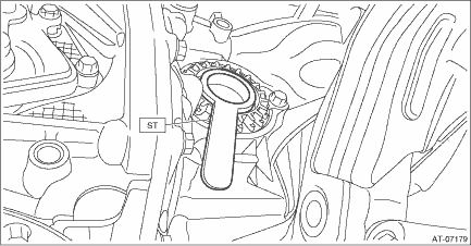
1. Attach the ST to converter case.
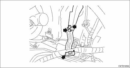
2. Replace the front differential side retainer oil seal. Differential Side Retainer Oil Seal > REPLACEMENT NOTE: • Be sure to replace the differential side retainer oil seal with a new part whenever the front drive shaft is removed from the transmission. • When a new differential side retainer oil seal has been installed, replacement is not required. 3. Install the cushion rubber on the transmission. Transmission Mounting System > INSTALLATION 4. Mount the transmission onto the transmission jack. 5. Strike and bend the transmission hanger of transmission rear with a soft rubber hammer etc. so that it gets in contact with the transmission case. CAUTION: Do not apply extra overload or impact to the transmission case.
6. While lifting up the transmission gradually, install the transmission to the engine. CAUTION: This operation requires at least two persons. NOTE: Keep the engine level. 7. Install the two engine connecting bolts and two nuts (lower side). Tightening torque: 50 N·m (5.1 kgf-m, 36.9 ft-lb)
8. Install the transmission rear crossmember. Transmission Mounting System > INSTALLATION 9. Install the hanger bracket. Tightening torque: 23 N·m (2.3 kgf-m, 17.0 ft-lb) 10. Remove the transmission jack. 11. Lower the vehicle. 12. Remove the ST (ENGINE HANGER). 13. Install the three engine mounting bolts (upper side). Tightening torque: 50 N·m (5.1 kgf-m, 36.9 ft-lb)
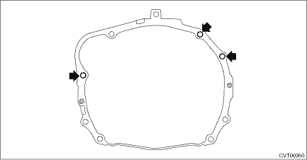
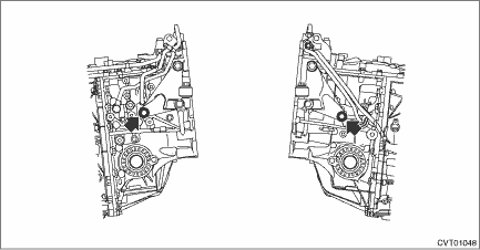
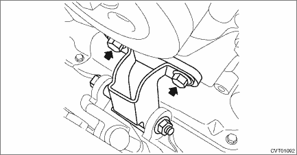
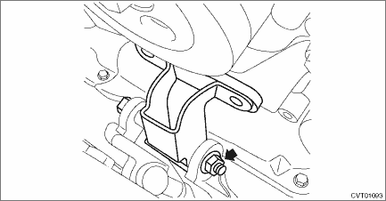
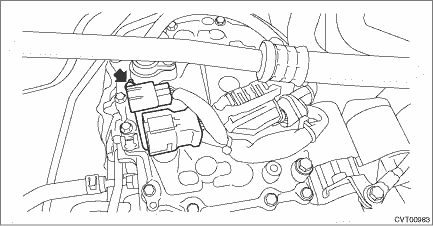
14. Install the transmission mounting bracket LH and RH. NOTE: • Install to the left side of vehicle first because the engine inclines to the left. • Temporarily tighten the bolt arrowed in the figure. Tightening torque: 75 N·m (7.6 kgf-m, 55.3 ft-lb)
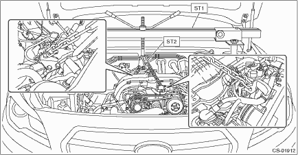
15. Set the ST to vehicle body and lift up the engine unit slightly.
CAUTION: • Set so that the chain sling does not contact the engine parts. • Set the arms of ST (ENGINE HANGER) at the locations shown in the figure.
16. Remove the bolts from ST (ST H4 (FA, FB)).
17. Remove the bolt and nut to remove ST (ST H4 (FA, FB)).
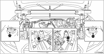
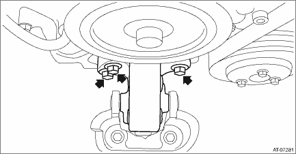
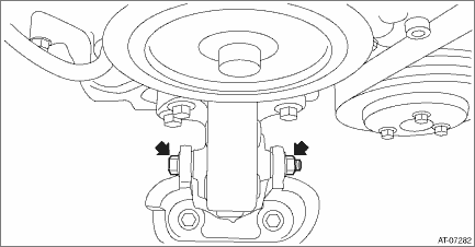
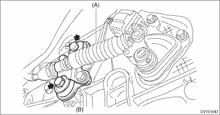
18. Temporarily attach the front cushion rubber with bolts.
19. Install the bolt and nut to the front cushion rubber.
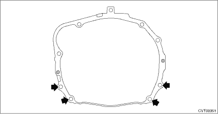
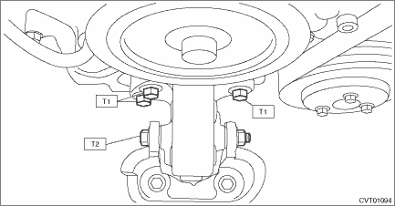
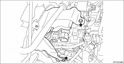
20. Tighten the bolts and nuts of front cushion rubber. NOTE: Always start tightening from the bolts on the engine side. Tightening torque: T1: 25 N·m (2.5 kgf-m, 18.4 ft-lb) T2: 45 N·m (4.6 kgf-m, 33.2 ft-lb)
21. Remove the ST (ENGINE HANGER and CHAIN SLING) and the bolt of φ8 mm (0.3 in). 22. Install the V-belt cover. Tightening torque: 6.5 N·m (0.7 kgf-m, 4.7 ft-lb) 23. Install the nut to the transmission mounting bracket. Tightening torque: 45 N·m (4.6 kgf-m, 33.2 ft-lb)
24. Install the transmission harness stay. Tightening torque: 7 N·m (0.7 kgf-m, 5.2 ft-lb)
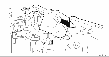
25. Install the TCM. Transmission Control Module (TCM) > INSTALLATION 26. Insert the transmission case cover (small) between transmission case cover (large) and transmission to install. NOTE: When inserting, be careful that the insulator inside transmission case cover is not turned over. Tightening torque: 7 N·m (0.7 kgf-m, 5.3 ft-lb)
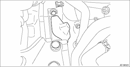
27. Remove the ST (STOPPER SET) from converter case. 28. Match the torque converter screw hole with drive plate hole to install the bolt. CAUTION: • Do not drop the mounting bolt in the converter housing. • Do not damage the mounting bolt. Tightening torque: 25 N·m (2.5 kgf-m, 18.4 ft-lb) 29. Install the remaining three bolts by rotating the crank pulley a little at a time in the same direction as engine revolution. Tightening torque: 25 N·m (2.5 kgf-m, 18.4 ft-lb) 30. Install the service hole plug.
31. Install the starter. Starter > INSTALLATION 32. Lift up the vehicle. 33. Tighten the single mounting bolt of transmission mounting bracket. Tightening torque: 75 N·m (7.6 kgf-m, 55.3 ft-lb)
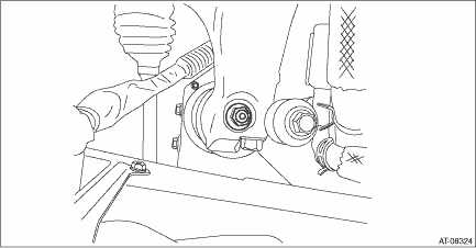
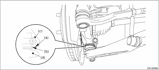
34. Set the ST to differential side retainer.
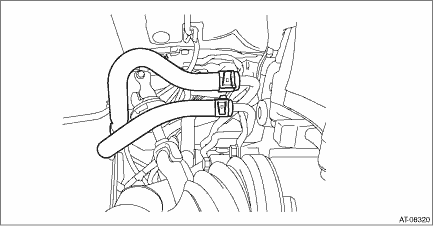
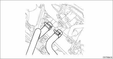
35. Replace the circlip of the drive shaft with a new part. 36. Insert the front drive shaft spline section into transmission and remove the ST (OIL SEAL PROTECTOR). 37. Insert the drive shaft into the transmission securely by pressing the housing from outside of the vehicle. 38. Install the CVTF CVT inlet hose and CVTF CVT outlet hose. (With CVTF cooler (air cool)) NOTE: Use new CVTF CVT inlet hose and CVTF CVT outlet hose.
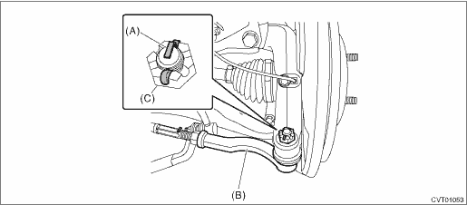
39. Insert the ball joint into housing and secure with bolt. CAUTION: • Before tightening, make sure the bottom surface of the housing assembly - front axle and the stepped section of ball joint are in contact. • Be careful not to damage the boot of the joint. Tightening torque: 50 N·m (5.1 kgf-m, 36.9 ft-lb)
40. Install the stabilizer link. Tightening torque: 60 N·m (6.1 kgf-m, 44.3 ft-lb) 41. Connect the tie-rod end and knuckle arm, and attach the castle nut. CAUTION: When connecting the tie-rod end, do not hit the cap at the bottom of tie-rod end with a hammer. Tightening torque: 27 N·m (2.8 kgf-m, 19.9 ft-lb) 42. After tightening the castle nut to the specified tightening torque, tighten it further within 60° until the cotter pin hole is aligned with slot in the nut. Fit the cotter pin into the nut, and then bend the pin to lock.
43. Install the propeller shaft. Propeller Shaft > INSTALLATION 44. Install the universal joint. Universal Joint > INSTALLATION 45. Install the plate assembly to transmission. Tightening torque: 25 N·m (2.5 kgf-m, 18.4 ft-lb)
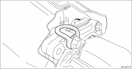
46. Install the washer and snap pin to the shifter arm.
47. Install the center exhaust cover. Tightening torque: 18 N·m (1.8 kgf-m, 13.3 ft-lb) 48. Install the center exhaust pipe. Center Exhaust Pipe > INSTALLATION 49. Install the under cover - front. 50. Lower the vehicle. 51. Install the front tire LH and RH. Tire and Wheel > INSTALLATION 52. Replace the CVTF inlet hose and CVTF outlet hose with new parts. CVTF Cooler (With Warmer Function) 53. Install the CVTF inlet hose and CVTF outlet hose. (Without CVTF cooler (air cool))
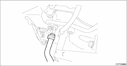
54. Install the CVTF outlet hose. (With CVTF cooler (air cool))
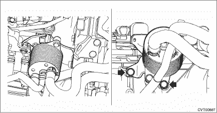
55. Install the CVTF cooler (with warmer feature). Tightening torque: 23 N·m (2.3 kgf-m, 17.0 ft-lb)
56. Install the CVTF cooler hose. (With CVTF cooler (air cool))
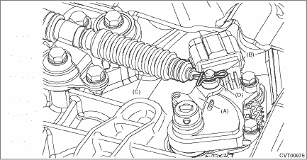
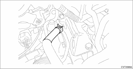
57. Connect the harness connector, and install the clip and transmission radio ground cord terminal. Tightening torque: 13 N·m (1.3 kgf-m, 9.6 ft-lb)
58. Install the battery cable bracket, and install the battery cable clip to the bracket. Tightening torque: 7.5 N·m (0.76 kgf-m, 5.5 ft-lb)
59. Install the air intake boot assembly. Air Intake Boot > INSTALLATION 60. Install the air intake duct. Air Intake Duct > INSTALLATION 61. Connect the battery ground terminal. 62. Refill differential gear oil to adjust the differential gear oil amount. Differential Gear Oil 63. Refill CVTF to adjust the CVTF amount. CVTF 64. Perform the operation for clearing AT learning value. Clear Memory Mode 65. Perform the operation of AT learning mode. Learning Control 66. Execute the rear differential inspection mode. Rear Differential Inspection Mode CAUTION: Always execute the rear differential inspection mode at the replacement of the following. • Replacement of transmission assembly • Replacement of front differential hypoid gear set 67. Perform the road test to make sure there is no fault. Road Test > INSPECTION |
 Removal
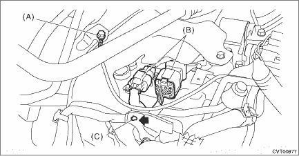
1. Disconnect the ground terminal from battery sensor. NOTE2. Lock the steering wheel.3. Remove the air intake duct. Air Intake Duct > REMOVAL4. Remove the clip (A), and loosen the clamps (B) and (C ...

Other materials:
Removal
1. Remove the sun visor assembly.(1) Detach the cover, and remove the screws.(2) Disconnect the connector, and remove the sun visor assembly.2. Remove the hook - sun visor.(1) Press both sides using a flat tip screwdriver.(2) Remove the hook - sun visor by pulling it toward you. ...
