Subaru Legacy BN/BS (2015-2019) Service Manual: Dtc p0560 system voltage
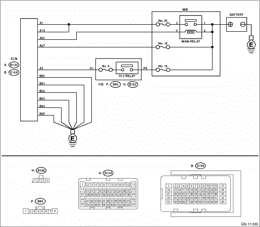
DTC DETECTING CONDITION: Immediately at fault recognition CAUTION: After servicing or replacing faulty parts, perform Clear Memory Mode Clear Memory Mode > OPERATION, and Inspection Mode Inspection Mode > PROCEDURE. WIRING DIAGRAM: • Engine Electrical System ENGINE TYPE EZ (WITHOUT PUSH BUTTON START) Engine Electrical System > WIRING DIAGRAM • Engine Electrical System ENGINE TYPE EZ (WITH PUSH BUTTON START) Engine Electrical System > WIRING DIAGRAM
1. OUTLINE OF DIAGNOSIS Detect the open/short circuit of back-up power supply circuit. Judge as NG when the backup power voltage is low. 2. EXECUTION CONDITION
3. GENERAL DRIVING CYCLE Always perform the diagnosis continuously. 4. DIAGNOSTIC METHOD If the duration of time while the following conditions are met is longer than the time indicated, judge as NG.
Time Needed for Diagnosis: 2500 ms Malfunction Indicator Light Illumination: Illuminates as soon as a malfunction occurs. |
 Dtc p0050 a/f / o2 heater control circuit bank 2 sensor 1
DTC DETECTING CONDITION:Detected when two consecutive driving cycles with fault occur.CAUTION:After servicing or replacing faulty parts, perform Clear Memory Mode Clear Memory Mode > OPERATION, and I ...
 Dtc p0852 park/neutral switch input circuit high
DTC DETECTING CONDITION:Detected when two consecutive driving cycles with fault occur.TROUBLE SYMPTOM:Improper idlingCAUTION:After servicing or replacing faulty parts, perform Clear Memory Mode Clear ...
Other materials:
Specification
1. DATA COMMUNICATION MODULE (DCM)Terminal No.DescriptionMeasuring conditionStandardA1 — — — A2 — — — A3LED GREEN — — A4 ←> Chassis groundi-buttoni-button OFF > ON1 M- or more > less than 1 -A5 ←> Chassis groundSOS buttonSOS button OFF > ON1 M- or more > less than 1 -A ...
