Subaru Legacy BN/BS (2015-2019) Service Manual: Dtc p0050 a/f / o2 heater control circuit bank 2 sensor 1
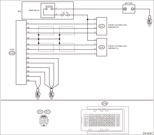
DTC DETECTING CONDITION: Detected when two consecutive driving cycles with fault occur. CAUTION: After servicing or replacing faulty parts, perform Clear Memory Mode Clear Memory Mode > OPERATION, and Inspection Mode Inspection Mode > PROCEDURE. WIRING DIAGRAM: • Engine Electrical System ENGINE TYPE EZ (WITHOUT PUSH BUTTON START) Engine Electrical System > WIRING DIAGRAM • Engine Electrical System ENGINE TYPE EZ (WITH PUSH BUTTON START) Engine Electrical System > WIRING DIAGRAM
1. OUTLINE OF DIAGNOSIS NOTE: For the detection standard, refer to DTC P0030. Diagnostic Procedure with Diagnostic Trouble Code (DTC) > DTC P0030 A/F / O2 HEATER CONTROL CIRCUIT BANK 1 SENSOR 1 |
 Dtc p0051 a/f / o2 heater control circuit low bank 2 sensor 1
DTC DETECTING CONDITION:Immediately at fault recognitionCAUTION:After servicing or replacing faulty parts, perform Clear Memory Mode Clear Memory Mode > OPERATION, and Inspection Mode Inspection Mod ...
 Dtc p0560 system voltage
DTC DETECTING CONDITION:Immediately at fault recognitionCAUTION:After servicing or replacing faulty parts, perform Clear Memory Mode Clear Memory Mode > OPERATION, and Inspection Mode Inspection Mod ...
Other materials:
Making a call
There are several methods by which a call
can be made, as described below.
Press the HOME button on the audio
panel.
Touch the "PHONE" key.
Select the desired key to make a call
from the list.
Item
Function
Incoming
Calls
Display ...
