Subaru Legacy BN/BS (2015-2019) Service Manual: Dtc p0051 a/f / o2 heater control circuit low bank 2 sensor 1
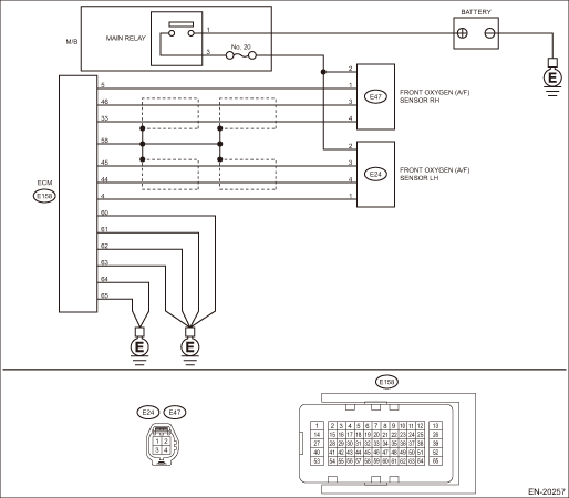
DTC DETECTING CONDITION: Immediately at fault recognition CAUTION: After servicing or replacing faulty parts, perform Clear Memory Mode Clear Memory Mode > OPERATION, and Inspection Mode Inspection Mode > PROCEDURE. WIRING DIAGRAM: • Engine Electrical System ENGINE TYPE EZ (WITHOUT PUSH BUTTON START) Engine Electrical System > WIRING DIAGRAM • Engine Electrical System ENGINE TYPE EZ (WITH PUSH BUTTON START) Engine Electrical System > WIRING DIAGRAM
1. OUTLINE OF DIAGNOSIS NOTE: For the detection standard, refer to DTC P0031. Diagnostic Procedure with Diagnostic Trouble Code (DTC) > DTC P0031 A/F / O2 HEATER CONTROL CIRCUIT LOW BANK 1 SENSOR 1 |
 Dtc p0052 a/f / o2 heater control circuit high bank 2 sensor 1
DTC DETECTING CONDITION:Immediately at fault recognitionCAUTION:After servicing or replacing faulty parts, perform Clear Memory Mode Clear Memory Mode > OPERATION, and Inspection Mode Inspection Mod ...
 Dtc p0050 a/f / o2 heater control circuit bank 2 sensor 1
DTC DETECTING CONDITION:Detected when two consecutive driving cycles with fault occur.CAUTION:After servicing or replacing faulty parts, perform Clear Memory Mode Clear Memory Mode > OPERATION, and I ...
Other materials:
Removal
1. Disconnect the ground terminal from battery sensor. NOTE2. Remove the roof spoiler. Roof Spoiler > REMOVAL3. Remove the trim panel - rear gate and the motor assembly - rear wiper. Rear Wiper Motor > REMOVAL4. Disconnect the rear defogger connector.5. Remove the touch sensor LWR. (Model with po ...
