Subaru Legacy BN/BS (2015-2019) Service Manual: Dtc p0052 a/f / o2 heater control circuit high bank 2 sensor 1
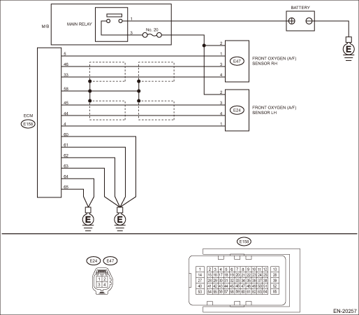
DTC DETECTING CONDITION: Immediately at fault recognition CAUTION: After servicing or replacing faulty parts, perform Clear Memory Mode Clear Memory Mode > OPERATION, and Inspection Mode Inspection Mode > PROCEDURE. WIRING DIAGRAM: • Engine Electrical System ENGINE TYPE EZ (WITHOUT PUSH BUTTON START) Engine Electrical System > WIRING DIAGRAM • Engine Electrical System ENGINE TYPE EZ (WITH PUSH BUTTON START) Engine Electrical System > WIRING DIAGRAM
1. OUTLINE OF DIAGNOSIS NOTE: For the detection standard, refer to DTC P0032. Diagnostic Procedure with Diagnostic Trouble Code (DTC) > DTC P0032 A/F / O2 HEATER CONTROL CIRCUIT HIGH BANK 1 SENSOR 1 |
 Dtc p0057 a/f / o2 heater control circuit low bank 2 sensor 2
DTC DETECTING CONDITION:Detected when two consecutive driving cycles with fault occur.CAUTION:After servicing or replacing faulty parts, perform Clear Memory Mode Clear Memory Mode > OPERATION, and I ...
 Dtc p0051 a/f / o2 heater control circuit low bank 2 sensor 1
DTC DETECTING CONDITION:Immediately at fault recognitionCAUTION:After servicing or replacing faulty parts, perform Clear Memory Mode Clear Memory Mode > OPERATION, and Inspection Mode Inspection Mod ...
Other materials:
Dtc c1985 forbidden state of dynamic actuator operation
DTC DETECTING CONDITION:This malfunction is stored if dynamic parking through the electronic parking brake actuator does not operate.TROUBLE SYMPTOM:Parking brake system does not operate.STEPCHECKYESNO1.CHECK DETECTION OF OTHER DTCS FOR VDC. Read Diagnostic Trouble Code (DTC)Is any other DTC display ...
