Subaru Legacy BN/BS (2015-2019) Service Manual: Dtc p0057 a/f / o2 heater control circuit low bank 2 sensor 2
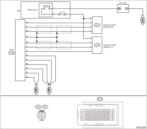
DTC DETECTING CONDITION: Detected when two consecutive driving cycles with fault occur. CAUTION: After servicing or replacing faulty parts, perform Clear Memory Mode Clear Memory Mode > OPERATION, and Inspection Mode Inspection Mode > PROCEDURE. WIRING DIAGRAM: • Engine Electrical System ENGINE TYPE EZ (WITHOUT PUSH BUTTON START) Engine Electrical System > WIRING DIAGRAM • Engine Electrical System ENGINE TYPE EZ (WITH PUSH BUTTON START) Engine Electrical System > WIRING DIAGRAM
1. OUTLINE OF DIAGNOSIS NOTE: For the detection standard, refer to DTC P0037. Diagnostic Procedure with Diagnostic Trouble Code (DTC) > DTC P0037 A/F / O2 HEATER CONTROL CIRCUIT LOW BANK 1 SENSOR 2 |
 Dtc p0058 a/f / o2 heater control circuit low bank 2 sensor 2
DTC DETECTING CONDITION:Detected when two consecutive driving cycles with fault occur.CAUTION:After servicing or replacing faulty parts, perform Clear Memory Mode Clear Memory Mode > OPERATION, and I ...
 Dtc p0052 a/f / o2 heater control circuit high bank 2 sensor 1
DTC DETECTING CONDITION:Immediately at fault recognitionCAUTION:After servicing or replacing faulty parts, perform Clear Memory Mode Clear Memory Mode > OPERATION, and Inspection Mode Inspection Mod ...
Other materials:
System operation check mode operation
1. On «Start» display, select «Diagnosis».2. On «Vehicle selection» display, input the target vehicle information and select «Confirmed».3. On «Main Menu» display, select «Each System».4. On «Select System» display, select «Keyless Access with Push Button Start» and then select «Ent ...
