DTC DETECTING CONDITION: Immediately at fault recognition TROUBLE SYMPTOM: • Excessive shift shock • Shift characteristics malfunction 1. ENGINE TYPE FB WIRING DIAGRAM: CVT control system CVT Control System > WIRING DIAGRAM 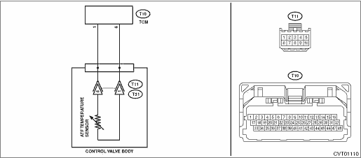
| STEP | CHECK | YES | NO | 1.CHECK HARNESS. 1) Turn the ignition switch to ON. 2) Measure the voltage between TCM connectors. Connector & terminal (T10) No. 6 (+) — (T10) No. 1 (−): | Is the voltage 5 V or more- | Repair the short circuit of harness. | Diagnostic Procedure with Diagnostic Trouble Code (DTC) > DTC P0713 TRANSMISSION FLUID TEMPERATURE SENSOR "A" CIRCUIT HIGH | 2.CHECK ATF TEMPERATURE SENSOR. 1) Turn the ignition switch to OFF. 2) Disconnect the TCM connector. 3) Measure the resistance between TCM connector terminals. | Is the resistance 1 M- or more- | Repair the open circuit of transmission harness. | Diagnostic Procedure with Diagnostic Trouble Code (DTC) > DTC P0713 TRANSMISSION FLUID TEMPERATURE SENSOR "A" CIRCUIT HIGH | 3.CHECK ATF TEMPERATURE SENSOR. 1) Connect the connector to TCM. 3) Warm up until the ATF temperature exceeds 50°C (122°F). 4) Turn the ignition switch to OFF. 5) Disconnect the TCM connector. 6) Measure the resistance between TCM connector terminals. | Is the resistance 650 — 990 -- | Diagnostic Procedure with Diagnostic Trouble Code (DTC) > DTC P0713 TRANSMISSION FLUID TEMPERATURE SENSOR "A" CIRCUIT HIGH | Diagnostic Procedure with Diagnostic Trouble Code (DTC) > DTC P0713 TRANSMISSION FLUID TEMPERATURE SENSOR "A" CIRCUIT HIGH | 4.CHECK ATF TEMPERATURE SENSOR. Measure the resistance between TCM connector terminals. | Does the resistance value increase gradually while the ATF temperature decreases- | Diagnostic Procedure with Diagnostic Trouble Code (DTC) > DTC P0713 TRANSMISSION FLUID TEMPERATURE SENSOR "A" CIRCUIT HIGH | Replace the control valve body. Control Valve Body | 5.CHECK INPUT SIGNAL FOR TCM. 1) Connect the connector to TCM. 2) Turn the ignition switch to ON. (Do not start engine.) 3) Read the data of «ATF Temp.» using the Subaru Select Monitor. | Does the ATF temperature gradually decrease- | Check for poor contact of the ATF temperature sensor and TCM connector harness, and repair the defective part. | Diagnostic Procedure with Diagnostic Trouble Code (DTC) > DTC P0713 TRANSMISSION FLUID TEMPERATURE SENSOR "A" CIRCUIT HIGH | 6.CHECK FOR POOR CONTACT. | Is there poor contact of ATF temperature sensor circuit- | | Replace the TCM. Transmission Control Module (TCM) |
2. ENGINE TYPE EZ WIRING DIAGRAM: CVT control system CVT Control System > WIRING DIAGRAM 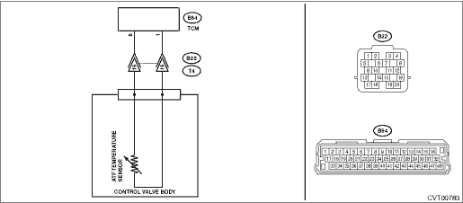
| STEP | CHECK | YES | NO | 1.CHECK HARNESS. 1) Turn the ignition switch to ON. 2) Measure the voltage between TCM connectors. Connector & terminal (B54) No. 6 (+) — (B54) No. 1 (−): | Is the voltage 5 V or more- | Repair the short circuit of harness. | Diagnostic Procedure with Diagnostic Trouble Code (DTC) > DTC P0713 TRANSMISSION FLUID TEMPERATURE SENSOR "A" CIRCUIT HIGH | 2.CHECK HARNESS. 1) Turn the ignition switch to OFF. 2) Disconnect the TCM and transmission connectors. 3) Measure the resistance between TCM connector and transmission connectors. Connector & terminal (B54) No. 6 — (B22) No. 16: (B54) No. 1 — (B22) No. 19: | Is the resistance less than 1 -- | Diagnostic Procedure with Diagnostic Trouble Code (DTC) > DTC P0713 TRANSMISSION FLUID TEMPERATURE SENSOR "A" CIRCUIT HIGH | Repair the open circuit of body harness. | 3.CHECK ATF TEMPERATURE SENSOR. Measure the resistance between transmission connector terminals. | Is the resistance 1 M- or more- | Repair the open circuit of transmission harness. | Diagnostic Procedure with Diagnostic Trouble Code (DTC) > DTC P0713 TRANSMISSION FLUID TEMPERATURE SENSOR "A" CIRCUIT HIGH | 4.CHECK ATF TEMPERATURE SENSOR. 1) Connect the connectors to TCM and transmission. 3) Warm up until the ATF temperature exceeds 50°C (122°F). 4) Turn the ignition switch to OFF. 5) Disconnect the transmission connector. 6) Measure the resistance between transmission connector terminals. | Is the resistance 730 — 1120 -- | Diagnostic Procedure with Diagnostic Trouble Code (DTC) > DTC P0713 TRANSMISSION FLUID TEMPERATURE SENSOR "A" CIRCUIT HIGH | Diagnostic Procedure with Diagnostic Trouble Code (DTC) > DTC P0713 TRANSMISSION FLUID TEMPERATURE SENSOR "A" CIRCUIT HIGH | 5.CHECK ATF TEMPERATURE SENSOR. Measure the resistance between transmission connector terminals. | Does the resistance value increase gradually while the ATF temperature decreases- | Diagnostic Procedure with Diagnostic Trouble Code (DTC) > DTC P0713 TRANSMISSION FLUID TEMPERATURE SENSOR "A" CIRCUIT HIGH | Replace the control valve body. Control Valve Body | 6.CHECK INPUT SIGNAL FOR TCM. 1) Connect the connector to transmission. 2) Turn the ignition switch to ON. (Do not start engine.) 3) Read the data of «ATF Temp.» using the Subaru Select Monitor. | Does the ATF temperature gradually decrease- | Check for poor contact of the ATF temperature sensor and transmission connector harness, and repair the defective part. | Diagnostic Procedure with Diagnostic Trouble Code (DTC) > DTC P0713 TRANSMISSION FLUID TEMPERATURE SENSOR "A" CIRCUIT HIGH | 7.CHECK FOR POOR CONTACT. | Is there poor contact of ATF temperature sensor circuit- | | Replace the TCM. Transmission Control Module (TCM) |
3. OUTLINE OF DIAGNOSIS (ENGINE TYPE FB) • Detect short circuit to power supply or open circuit of the oil temperature sensor 5 V system. • Judge as NG if the voltage detected by the oil temperature sensor is higher than the predetermined value. 4. EXECUTION CONDITION (ENGINE TYPE FB) Secondary Parameters | Execution condition | 12 V battery system voltage | ≥ 9 V | Vehicle speed (calculated from secondary pulley speed) | ≥ 6.3 MPH | Above condition satisfied for | ≥ 50 s |
5. DIAGNOSTIC METHOD (ENGINE TYPE FB) If the duration of time while the following conditions are met is longer than the time indicated, judge as NG. Judgment ValueMalfunction Criteria | Threshold Value | Measured Transmission fluid temperature sensor input voltage | > 4.507 V | (Transmission fluid temperature) | (< − 52 degC) | Time Needed for Diagnosis: 1 second Malfunction Indicator Light Illumination: Illuminates as soon as a malfunction occurs. 6. OUTLINE OF DIAGNOSIS (ENGINE TYPE EZ) • Detect short circuit to power supply or open circuit of the oil temperature sensor 5 V system. • Judge as NG if the voltage detected by the oil temperature sensor is higher than the predetermined value. 7. EXECUTION CONDITION (ENGINE TYPE EZ) Secondary Parameters | Execution condition | 12 V battery system voltage | ≥ 9 V | Vehicle speed (calculated from output shaft speed) | ≥ 6.3 MPH | Above condition satisfied for | ≥ 50 s |
8. DIAGNOSTIC METHOD (ENGINE TYPE EZ) If the duration of time while the following conditions are met is longer than the time indicated, judge as NG. Judgment ValueMalfunction Criteria | Threshold Value | Measured Transmission fluid temperature sensor input voltage | > 4.502 V | (Transmission fluid temperature) | (< − 53 degC) | Time Needed for Diagnosis: 1 second Malfunction Indicator Light Illumination: Illuminates as soon as a malfunction occurs. |  Dtc p0716 input/turbine shaft speed sensor "a" circuit range/performance
 Dtc p0712 transmission fluid temperature sensor "a" circuit low