
Subaru Legacy BN/BS (2015-2019) Service Manual: Dtc p081a starter disable circuit low
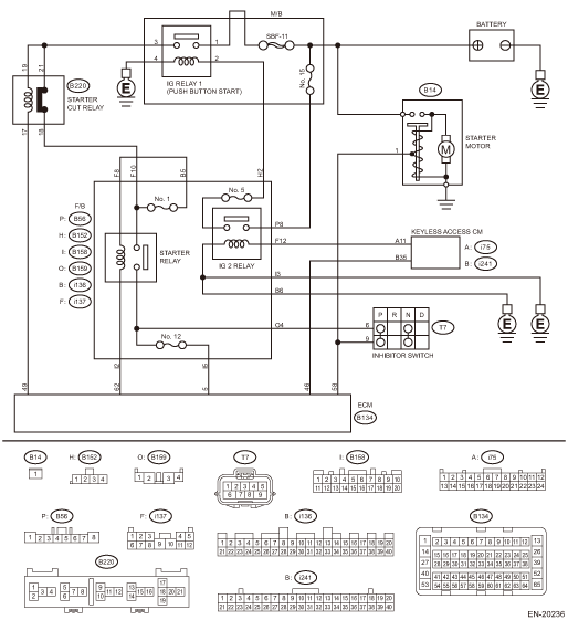
DTC DETECTING CONDITION: Immediately at fault recognition TROUBLE SYMPTOM: Failure of engine to start CAUTION: After servicing or replacing faulty parts, perform Clear Memory Mode Clear Memory Mode > OPERATION, and Inspection Mode Inspection Mode > PROCEDURE. WIRING DIAGRAM: Engine Electrical System ENGINE TYPE FB (WITH PUSH BUTTON START) Engine Electrical System > WIRING DIAGRAM
1. OUTLINE OF DIAGNOSIS Detect abnormal continuity in the starter cut relay. Judge as NG when the starter cut relay output line is open. 2. EXECUTION CONDITION
3. GENERAL DRIVING CYCLE Perform the diagnosis only once after the enable conditions have been established. 4. DIAGNOSTIC METHOD Judge as NG when the following conditions are established.
Time Needed for Diagnosis: Less than 1 second Malfunction Indicator Light Illumination: Illuminates as soon as a malfunction occurs. |
 Dtc p1160 throttle return spring
NOTE:For the diagnostic procedure, refer to DTC P2101. Diagnostic Procedure with Diagnostic Trouble Code (DTC) > DTC P2101 THROTTLE ACTUATOR "A" CONTROL MOTOR CIRCUIT RANGE/PERFORMANCE1. OUTLINE OF D ...
 Dtc p0700 transmission control system (mil request)
NOTE:For the diagnostic procedure, refer to AT section. Basic Diagnostic Procedure1. OUTLINE OF DIAGNOSISJudge as NG when there is CAN communication with the TCM and there is a MIL lighting request.2 ...
Other materials:
Dtc b1013 ignition power
DTC DETECTING CONDITION:Voltage failure caused by poor contact of IGN power supply circuitsIGN voltage was outside the range of 8.3 — 16.7 V, when the IGN power supply was ON.Time Needed for Diagnosis:40 s or moreTROUBLE SYMPTOM:Symptoms such as shift lock or wiper not operating may occur.WIRING D ...
