Subaru Legacy BN/BS (2015-2019) Service Manual: Dtc p2009 tgv control circuit low bank 1
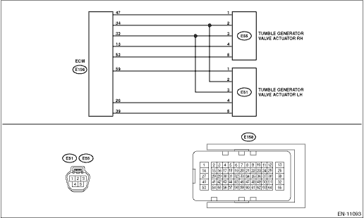
DTC DETECTING CONDITION: Immediately at fault recognition CAUTION: After servicing or replacing faulty parts, perform Clear Memory Mode Clear Memory Mode > OPERATION, and Inspection Mode Inspection Mode > PROCEDURE. WIRING DIAGRAM: • Engine Electrical System ENGINE TYPE FB (WITHOUT PUSH BUTTON START) Engine Electrical System > WIRING DIAGRAM • Engine Electrical System ENGINE TYPE FB (WITH PUSH BUTTON START) Engine Electrical System > WIRING DIAGRAM
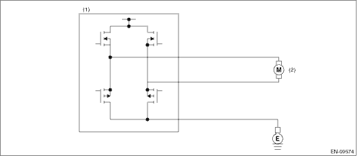
1. OUTLINE OF DIAGNOSIS Detect the open or short circuit of tumble generator valve motor. Judge as NG when the overcurrent signal is sent from IC after tumble generator valve driving IC diagnosis. 2. COMPONENT DESCRIPTION
3. EXECUTION CONDITION
4. GENERAL DRIVING CYCLE Perform the diagnosis continuously after the enable conditions have been established. 5. DIAGNOSTIC METHOD If the duration of time while the following conditions are met is longer than the time indicated, judge as NG.
Time Needed for Diagnosis: 96 ms - 10 time(s) Malfunction Indicator Light Illumination: Illuminates as soon as a malfunction occurs. |
 Dtc p2011 tgv control circuit/open bank 2
DTC DETECTING CONDITION:Immediately at fault recognitionCAUTION:After servicing or replacing faulty parts, perform Clear Memory Mode Clear Memory Mode > OPERATION, and Inspection Mode Inspection Mod ...
 Dtc p2008 tgv control circuit/open bank 1
DTC DETECTING CONDITION:Immediately at fault recognitionCAUTION:After servicing or replacing faulty parts, perform Clear Memory Mode Clear Memory Mode > OPERATION, and Inspection Mode Inspection Mod ...
Other materials:
Dtc b11f0 disposal process complete
DIAGNOSIS START CONDITION:Ignition voltage is 10 V to 16 V.DTC DETECTING CONDITION:Disposal process of airbag control module is completed.CAUTION:Before performing diagnosis, refer to “CAUTION” in “General Description”. General Description > CAUTIONSTEPCHECKYESNO1.CHECK DTC. ...
