Subaru Legacy BN/BS (2015-2019) Service Manual: Dtc p2011 tgv control circuit/open bank 2
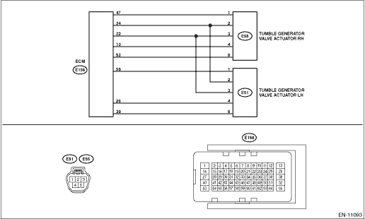
DTC DETECTING CONDITION: Immediately at fault recognition CAUTION: After servicing or replacing faulty parts, perform Clear Memory Mode Clear Memory Mode > OPERATION, and Inspection Mode Inspection Mode > PROCEDURE. WIRING DIAGRAM: • Engine Electrical System ENGINE TYPE FB (WITHOUT PUSH BUTTON START) Engine Electrical System > WIRING DIAGRAM • Engine Electrical System ENGINE TYPE FB (WITH PUSH BUTTON START) Engine Electrical System > WIRING DIAGRAM
1. OUTLINE OF DIAGNOSIS NOTE: For the detection standard, refer to DTC P2008. Diagnostic Procedure with Diagnostic Trouble Code (DTC) > DTC P2008 TGV CONTROL CIRCUIT/OPEN BANK 1 |
 Dtc p2012 tgv control circuit low bank 2
DTC DETECTING CONDITION:Immediately at fault recognitionCAUTION:After servicing or replacing faulty parts, perform Clear Memory Mode Clear Memory Mode > OPERATION, and Inspection Mode Inspection Mod ...
 Dtc p2009 tgv control circuit low bank 1
DTC DETECTING CONDITION:Immediately at fault recognitionCAUTION:After servicing or replacing faulty parts, perform Clear Memory Mode Clear Memory Mode > OPERATION, and Inspection Mode Inspection Mod ...
Other materials:
To temporarily cancel the cruise control
The cruise control can be temporarily
canceled in the following ways.
Press the "CANCEL" button.
Press the X-mode switch to activate
the X-mode (models with X-mode).
Depress the brake pedal.
Depress the clutch pedal (MT models).
WARNING
For CVT models, ...
