Subaru Legacy BN/BS (2015-2019) Service Manual: Dtc p2012 tgv control circuit low bank 2
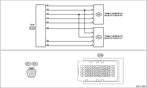
DTC DETECTING CONDITION: Immediately at fault recognition CAUTION: After servicing or replacing faulty parts, perform Clear Memory Mode Clear Memory Mode > OPERATION, and Inspection Mode Inspection Mode > PROCEDURE. WIRING DIAGRAM: • Engine Electrical System ENGINE TYPE FB (WITHOUT PUSH BUTTON START) Engine Electrical System > WIRING DIAGRAM • Engine Electrical System ENGINE TYPE FB (WITH PUSH BUTTON START) Engine Electrical System > WIRING DIAGRAM
1. OUTLINE OF DIAGNOSIS NOTE: For the detection standard, refer to DTC P2009. Diagnostic Procedure with Diagnostic Trouble Code (DTC) > DTC P2009 TGV CONTROL CIRCUIT LOW BANK 1 |
 Dtc p2016 tgv position sensor/switch circuit low bank 1
DTC DETECTING CONDITION:Immediately at fault recognitionTROUBLE SYMPTOM:• Improper idling• Engine stalls.• Poor driving performanceCAUTION:After servicing or replacing faulty parts, ...
 Dtc p2011 tgv control circuit/open bank 2
DTC DETECTING CONDITION:Immediately at fault recognitionCAUTION:After servicing or replacing faulty parts, perform Clear Memory Mode Clear Memory Mode > OPERATION, and Inspection Mode Inspection Mod ...
Other materials:
Dtc u0327 software incompatibility with vehicle security control module
DTC DETECTING CONDITION:No data is received from keyless access CM.TROUBLE SYMPTOM:Cooperation control of keyless access does not operate properly.STEPCHECKYESNO1.CHECK PERFORMING OF BASIC DIAGNOSTIC PROCEDURE.Was the basic diagnostic procedure performed up to STEP 8- Diagnostic Procedure with Diagn ...
