Subaru Legacy BN/BS (2015-2019) Service Manual: Dtc p2016 tgv position sensor/switch circuit low bank 1
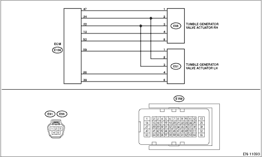
DTC DETECTING CONDITION: Immediately at fault recognition TROUBLE SYMPTOM: • Improper idling • Engine stalls. • Poor driving performance CAUTION: After servicing or replacing faulty parts, perform Clear Memory Mode Clear Memory Mode > OPERATION, and Inspection Mode Inspection Mode > PROCEDURE. WIRING DIAGRAM: • Engine Electrical System ENGINE TYPE FB (WITHOUT PUSH BUTTON START) Engine Electrical System > WIRING DIAGRAM • Engine Electrical System ENGINE TYPE FB (WITH PUSH BUTTON START) Engine Electrical System > WIRING DIAGRAM
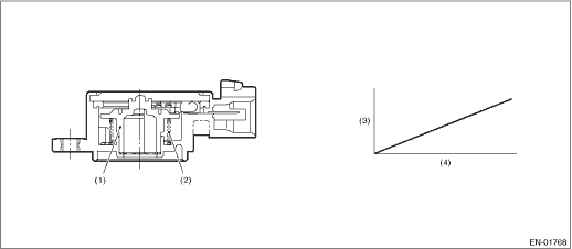
1. OUTLINE OF DIAGNOSIS Detect open or short circuit of tumble generator valve position sensor. Judge as NG if out of specification. 2. COMPONENT DESCRIPTION
3. EXECUTION CONDITION
4. GENERAL DRIVING CYCLE Always perform the diagnosis continuously. 5. DIAGNOSTIC METHOD If the duration of time while the following conditions are met is longer than the time indicated, judge as NG.
Time Needed for Diagnosis: 500 ms Malfunction Indicator Light Illumination: Illuminates as soon as a malfunction occurs. |
 Dtc p2017 tgv position sensor/switch circuit high bank 1
DTC DETECTING CONDITION:Immediately at fault recognitionTROUBLE SYMPTOM:• Improper idling• Engine stalls.• Poor driving performanceCAUTION:After servicing or replacing faulty parts, ...
 Dtc p2012 tgv control circuit low bank 2
DTC DETECTING CONDITION:Immediately at fault recognitionCAUTION:After servicing or replacing faulty parts, perform Clear Memory Mode Clear Memory Mode > OPERATION, and Inspection Mode Inspection Mod ...
Other materials:
Disassembly
1. FORWARD CLUTCH ASSEMBLY1. Remove the snap ring.2. Remove the retaining plate, drive plate, driven plate and dish plate.3. Compress the return spring using the ST to remove the snap ring.ST1 18762AA010COMPRESSOR SPECIAL TOOLST2 398673600COMPRESSOR4. Remove the chamber COMPL and snap ring.5. ...
