1.CHECK FOR ANY OTHER DTC ON DISPLAY. | Is any other DTC displayed- | Check DTC using “List of Diagnostic Trouble Code (DTC)”. List of Diagnostic Trouble Code (DTC) | Diagnostic Procedure with Diagnostic Trouble Code (DTC) > DTC P2097 POST CATALYST FUEL TRIM SYSTEM TOO RICH BANK 1 |
2.CHECK FRONT OXYGEN (A/F) SENSOR CONNECTOR AND COUPLING CONNECTOR. | Has water entered the connector- | Completely remove any water inside. | Diagnostic Procedure with Diagnostic Trouble Code (DTC) > DTC P2097 POST CATALYST FUEL TRIM SYSTEM TOO RICH BANK 1 |
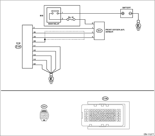
3.CHECK HARNESS BETWEEN ECM AND FRONT OXYGEN (A/F) SENSOR CONNECTOR. 1) Turn the ignition switch to OFF. 2) Disconnect the connectors from ECM and front oxygen (A/F) sensor. 3) Measure the resistance of harness between ECM connector and front oxygen (A/F) sensor connector. Connector & terminal (E158) No. 46 — (E24) No. 3: (E158) No. 33 — (E24) No. 4: | Is the resistance less than 1 -- | Diagnostic Procedure with Diagnostic Trouble Code (DTC) > DTC P2097 POST CATALYST FUEL TRIM SYSTEM TOO RICH BANK 1 | Repair the open circuit of harness between ECM connector and front oxygen (A/F) sensor connector. |
4.CHECK HARNESS BETWEEN ECM AND FRONT OXYGEN (A/F) SENSOR CONNECTOR. Measure the resistance between ECM connector and chassis ground. Connector & terminal (E158) No. 46 — Chassis ground: (E158) No. 33 — Chassis ground: | Is the resistance 1 M- or more- | Diagnostic Procedure with Diagnostic Trouble Code (DTC) > DTC P2097 POST CATALYST FUEL TRIM SYSTEM TOO RICH BANK 1 | Repair the short circuit to ground in harness between ECM connector and front oxygen (A/F) sensor connector. |
5.CHECK OUTPUT SIGNAL FOR ECM. 1) Connect the connector to ECM. 2) Turn the ignition switch to ON. 3) Measure the voltage between front oxygen (A/F) sensor connector and chassis ground. Connector & terminal (E24) No. 3 (+) — Chassis ground (−): | Is the voltage 4.5 V or more- | Diagnostic Procedure with Diagnostic Trouble Code (DTC) > DTC P2097 POST CATALYST FUEL TRIM SYSTEM TOO RICH BANK 1 | Diagnostic Procedure with Diagnostic Trouble Code (DTC) > DTC P2097 POST CATALYST FUEL TRIM SYSTEM TOO RICH BANK 1 |
6.CHECK OUTPUT SIGNAL FOR ECM. Measure the voltage between front oxygen (A/F) sensor connector and chassis ground. Connector & terminal (E24) No. 4 (+) — Chassis ground (−): | Is the voltage 4.95 V or more- | Diagnostic Procedure with Diagnostic Trouble Code (DTC) > DTC P2097 POST CATALYST FUEL TRIM SYSTEM TOO RICH BANK 1 | Diagnostic Procedure with Diagnostic Trouble Code (DTC) > DTC P2097 POST CATALYST FUEL TRIM SYSTEM TOO RICH BANK 1 |
7.CHECK OUTPUT SIGNAL FOR ECM. Measure the voltage between front oxygen (A/F) sensor connector and chassis ground. Connector & terminal (E24) No. 3 (+) — Chassis ground (−): (E24) No. 4 (+) — Chassis ground (−): | Is the voltage 8 V or more- | Repair the short circuit to power in the harness between ECM connector and front oxygen (A/F) sensor connector. After repair, replace the ECM. Engine Control Module (ECM) | Repair the poor contact of ECM connector. |
| Are there holes or loose bolts on exhaust system- | Repair the exhaust system. | Diagnostic Procedure with Diagnostic Trouble Code (DTC) > DTC P2097 POST CATALYST FUEL TRIM SYSTEM TOO RICH BANK 1 |
9.CHECK AIR INTAKE SYSTEM. | Are there holes, loose bolts or disconnection of hose on air intake system- | Repair the air intake system. | Diagnostic Procedure with Diagnostic Trouble Code (DTC) > DTC P2097 POST CATALYST FUEL TRIM SYSTEM TOO RICH BANK 1 |
10.CHECK FUEL PRESSURE. WARNING: Place “NO OPEN FLAMES” signs near the working area. CAUTION: Be careful not to spill fuel. 1) Connect the front oxygen (A/F) sensor connector. 2) Measure the fuel pressure. Fuel Pressure > INSPECTION CAUTION: Before attaching/detaching a fuel pressure gauge, release the fuel pressure. | Is the measured value 340 — 400 kPa (3.5 — 4.1 kg/cm2, 49 — 58 psi)- | Diagnostic Procedure with Diagnostic Trouble Code (DTC) > DTC P2097 POST CATALYST FUEL TRIM SYSTEM TOO RICH BANK 1 | Check the fuel pump and fuel delivery line. Fuel Pump > INSPECTION Fuel Delivery and Evaporation Lines > INSPECTION |
11.CHECK ENGINE COOLANT TEMPERATURE SENSOR. 1) Start the engine and warm up completely. 2) Read the value of «Coolant Temp.» using the Subaru Select Monitor or a general scan tool. NOTE: • Subaru Select Monitor For detailed operation procedures, refer to “Read Current Data For Engine”. Subaru Select Monitor • General scan tool For detailed operation procedures, refer to the general scan tool operation manual. | Is the value of «Coolant Temp.» 75°C (167°F) or more- | Diagnostic Procedure with Diagnostic Trouble Code (DTC) > DTC P2097 POST CATALYST FUEL TRIM SYSTEM TOO RICH BANK 1 | Replace the engine coolant temperature sensor. Engine Coolant Temperature Sensor |
12.CHECK MASS AIR FLOW AND INTAKE AIR TEMPERATURE SENSOR. 1) Start the engine and warm up engine until coolant temperature is higher than 75°C (167°F). 2) For CVT models, set the select lever to “P” range or “N” range, and for MT models, place the shift lever in the neutral position. 3) Turn the A/C switch to OFF. 4) Turn all the accessory switches to OFF. 5) Read the value of «Mass Air Flow» using the Subaru Select Monitor or a general scan tool. NOTE: • Subaru Select Monitor For detailed operation procedures, refer to “Read Current Data For Engine”. Subaru Select Monitor • General scan tool For detailed operation procedures, refer to the general scan tool operation manual. | Is the value of «Mass Air Flow» 2.0 — 5.0 g/s (0.26 — 0.66 lb/m)- | Diagnostic Procedure with Diagnostic Trouble Code (DTC) > DTC P2097 POST CATALYST FUEL TRIM SYSTEM TOO RICH BANK 1 | Replace the mass air flow and intake air temperature sensor. Mass Air Flow and Intake Air Temperature Sensor |
13.CHECK MASS AIR FLOW AND INTAKE AIR TEMPERATURE SENSOR. 1) Start the engine and warm up engine until coolant temperature is higher than 75°C (167°F). 2) For CVT models, set the select lever to “P” range or “N” range, and for MT models, place the shift lever in the neutral position. 3) Turn the A/C switch to OFF. 4) Turn all the accessory switches to OFF. 6) Measure the ambient temperature. 7) Read the value of «Intake Air Temp.» using the Subaru Select Monitor or a general scan tool. NOTE: • Subaru Select Monitor For detailed operation procedures, refer to “Read Current Data For Engine”. Subaru Select Monitor • General scan tool For detailed operation procedures, refer to the general scan tool operation manual. | Subtract ambient temperature from «Intake Air Temp.». Is the obtained value −10 — 50°C (−18 — 90°F)- | Diagnostic Procedure with Diagnostic Trouble Code (DTC) > DTC P2097 POST CATALYST FUEL TRIM SYSTEM TOO RICH BANK 1 | Check the mass air flow and intake air temperature sensor. Mass Air Flow and Intake Air Temperature Sensor |
14.CHECK REAR OXYGEN SENSOR DATA. 1) Warm up the engine until engine coolant temperature is higher than 75°C (167°F), and keep the engine speed at 3,000 rpm. (2 minutes maximum) 2) Read the value of «Oxygen sensor #12» using the Subaru Select Monitor or a general scan tool. NOTE: • Depress the clutch pedal. (MT model) • Subaru Select Monitor For detailed operation procedures, refer to “Read Current Data For Engine”. Subaru Select Monitor • General scan tool For detailed operation procedures, refer to the general scan tool operation manual. | Is the value of «Oxygen sensor #12» 0.490 V or more- | Diagnostic Procedure with Diagnostic Trouble Code (DTC) > DTC P2097 POST CATALYST FUEL TRIM SYSTEM TOO RICH BANK 1 | Diagnostic Procedure with Diagnostic Trouble Code (DTC) > DTC P2097 POST CATALYST FUEL TRIM SYSTEM TOO RICH BANK 1 |
15.CHECK REAR OXYGEN SENSOR DATA. 1) Warm up the engine until engine coolant temperature is higher than 75°C (167°F), and rapidly reduce the engine speed from 3,000 rpm. 2) Read the value of «Oxygen sensor #12» using the Subaru Select Monitor or a general scan tool. NOTE: • Depress the clutch pedal. (MT model) • Subaru Select Monitor For detailed operation procedures, refer to “Read Current Data For Engine”. Subaru Select Monitor • General scan tool For detailed operation procedures, refer to the general scan tool operation manual. | Is the value of «Oxygen sensor #12» 0.250 V or less- | Diagnostic Procedure with Diagnostic Trouble Code (DTC) > DTC P2097 POST CATALYST FUEL TRIM SYSTEM TOO RICH BANK 1 | Diagnostic Procedure with Diagnostic Trouble Code (DTC) > DTC P2097 POST CATALYST FUEL TRIM SYSTEM TOO RICH BANK 1 |
16.CHECK REAR OXYGEN SENSOR CONNECTOR AND COUPLING CONNECTOR. | Has water entered the connector- | Completely remove any water inside. | Diagnostic Procedure with Diagnostic Trouble Code (DTC) > DTC P2097 POST CATALYST FUEL TRIM SYSTEM TOO RICH BANK 1 |
17.CHECK FRONT OXYGEN (A/F) SENSOR USING REAR OXYGEN SENSOR SIGNAL. 1) Warm up the engine until engine coolant temperature is higher than 75°C (167°F), then keep the engine idling for 5 minutes or more. 2) Read the value of «Oxygen sensor #12» using the Subaru Select Monitor or a general scan tool. NOTE: • Subaru Select Monitor For detailed operation procedures, refer to “Read Current Data For Engine”. Subaru Select Monitor • General scan tool For detailed operation procedures, refer to the general scan tool operation manual. | Is the value of «Oxygen sensor #12» 0.8 V or more for 5 minutes or more- | Replace the front oxygen (A/F) sensor. Front Oxygen (A/F) Sensor | Diagnostic Procedure with Diagnostic Trouble Code (DTC) > DTC P2097 POST CATALYST FUEL TRIM SYSTEM TOO RICH BANK 1 |
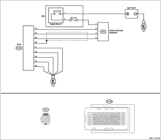
18.CHECK HARNESS BETWEEN ECM AND REAR OXYGEN SENSOR CONNECTOR. 1) Turn the ignition switch to OFF. 2) Disconnect the connector from ECM and rear oxygen sensor. 3) Measure the resistance of harness between ECM connector and rear oxygen sensor connector. Connector & terminal (E158) No. 57 — (E25) No. 3: (E158) No. 56 — (E25) No. 4: | Is the resistance less than 1 -- | Diagnostic Procedure with Diagnostic Trouble Code (DTC) > DTC P2097 POST CATALYST FUEL TRIM SYSTEM TOO RICH BANK 1 | Repair the open circuit of harness between ECM connector and rear oxygen sensor connector. |
19.CHECK HARNESS BETWEEN ECM AND REAR OXYGEN SENSOR CONNECTOR. 1) Connect the connector to ECM. 2) Turn the ignition switch to ON. 3) Measure the voltage between rear oxygen sensor connector and chassis ground. Connector & terminal (E25) No. 3 (+) — Chassis ground (−): | Is the voltage 0.2 — 0.5 V- | Replace the rear oxygen sensor. Rear Oxygen Sensor | Repair the harness and connector. NOTE: In this case, repair the following item: • Open circuit in harness between ECM connector and rear oxygen sensor connector • Poor contact of ECM connector |
 Dtc p2101 throttle actuator "a" control motor circuit range/performance
 Dtc p2096 post catalyst fuel trim system too lean bank 1