1.CHECK ELECTRONIC THROTTLE CONTROL RELAY. 1) Turn the ignition switch to OFF. 2) Remove the electronic throttle control relay. 3) Connect the battery to terminals No. 13 and No. 14 of electronic throttle control relay. 4) Measure the resistance between electronic throttle control relay terminals. | Is the resistance less than 1 -- | Diagnostic Procedure with Diagnostic Trouble Code (DTC) > DTC P2101 THROTTLE ACTUATOR "A" CONTROL MOTOR CIRCUIT RANGE/PERFORMANCE | Replace the electronic throttle control relay. Electronic Throttle Control Relay |
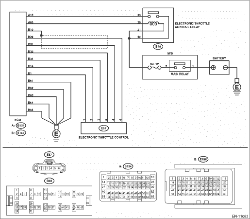
2.CHECK POWER SUPPLY OF ELECTRONIC THROTTLE CONTROL RELAY. Measure the voltage between electronic throttle control relay connector and chassis ground. Connector & terminal (B48) No. 22 (+) — Chassis ground (−): | Is the voltage 10 V or more- | Diagnostic Procedure with Diagnostic Trouble Code (DTC) > DTC P2101 THROTTLE ACTUATOR "A" CONTROL MOTOR CIRCUIT RANGE/PERFORMANCE | Repair the open or short to ground in the power supply circuit. |
3.CHECK HARNESS BETWEEN ECM AND ELECTRONIC THROTTLE CONTROL RELAY CONNECTOR. 1) Disconnect the connector from ECM. 2) Turn the ignition switch to ON. 3) Measure the voltage between electronic throttle control relay connector and chassis ground. Connector & terminal (B48) No. 20 (+) — Chassis ground (−): | Is the voltage 10 V or more- | Repair the short circuit to power in the harness between ECM connector and electronic throttle control relay connector. | Diagnostic Procedure with Diagnostic Trouble Code (DTC) > DTC P2101 THROTTLE ACTUATOR "A" CONTROL MOTOR CIRCUIT RANGE/PERFORMANCE |
4.CHECK HARNESS BETWEEN ECM AND ELECTRONIC THROTTLE CONTROL RELAY CONNECTOR. 1) Turn the ignition switch to OFF. 2) Measure the resistance between electronic throttle control relay connector and chassis ground. Connector & terminal (B48) No. 20 — Chassis ground: (B48) No. 23 — Chassis ground: | Is the resistance 1 M- or more- | Diagnostic Procedure with Diagnostic Trouble Code (DTC) > DTC P2101 THROTTLE ACTUATOR "A" CONTROL MOTOR CIRCUIT RANGE/PERFORMANCE | Repair the short circuit to ground in harness between ECM connector and electronic throttle control relay connector. |
5.CHECK HARNESS BETWEEN ECM AND ELECTRONIC THROTTLE CONTROL RELAY CONNECTOR. Measure the resistance between ECM connector and electronic throttle control relay connector. Connector & terminal (B134) No. 65 — (B48) No. 20: (B134) No. 13 — (B48) No. 23: | Is the resistance less than 1 -- | Diagnostic Procedure with Diagnostic Trouble Code (DTC) > DTC P2101 THROTTLE ACTUATOR "A" CONTROL MOTOR CIRCUIT RANGE/PERFORMANCE | Repair the open circuit in harness between ECM connector and electronic throttle control relay connector. |
6.CHECK HARNESS BETWEEN ECM AND ELECTRONIC THROTTLE CONTROL CONNECTOR. 1) Turn the ignition switch to OFF. 2) Disconnect the connectors from electronic throttle control. 3) Measure the resistance between ECM connector and chassis ground. Connector & terminal (E158) No. 32 — Chassis ground: (E158) No. 29 — Chassis ground: (E158) No. 29 — (E158) No. 19: (E158) No. 31 — Chassis ground: (E158) No. 31 — (E158) No. 19: | Is the resistance 1 M- or more- | Diagnostic Procedure with Diagnostic Trouble Code (DTC) > DTC P2101 THROTTLE ACTUATOR "A" CONTROL MOTOR CIRCUIT RANGE/PERFORMANCE | Repair the ground short circuit of harness between ECM connector and electronic throttle control connector. |
7.CHECK SHORT CIRCUIT INSIDE THE ECM. 1) Connect the connector to ECM. 2) Measure the resistance between electronic throttle control connector and engine ground. Connector & terminal (E57) No. 6 — Engine ground: (E57) No. 4 — Engine ground: | Is the resistance 1 M- or more- | Diagnostic Procedure with Diagnostic Trouble Code (DTC) > DTC P2101 THROTTLE ACTUATOR "A" CONTROL MOTOR CIRCUIT RANGE/PERFORMANCE | Repair the ground short circuit of harness between ECM connector and electronic throttle control connector. Replace the ECM if defective. Engine Control Module (ECM) |
8.CHECK HARNESS BETWEEN ECM AND ELECTRONIC THROTTLE CONTROL CONNECTOR. 1) Disconnect the connector from ECM. 2) Measure the resistance of harness between ECM connector and electronic throttle control connector. Connector & terminal (E158) No. 29 — (E57) No. 6: (E158) No. 31 — (E57) No. 4: (E158) No. 34 — (E57) No. 3: | Is the resistance less than 1 -- | Diagnostic Procedure with Diagnostic Trouble Code (DTC) > DTC P2101 THROTTLE ACTUATOR "A" CONTROL MOTOR CIRCUIT RANGE/PERFORMANCE | Repair the open circuit of harness between ECM connector and electronic throttle control connector. |
9.CHECK HARNESS BETWEEN ECM AND ELECTRONIC THROTTLE CONTROL CONNECTOR. 1) Connect the connector to ECM. 2) Measure the resistance between electronic throttle control connector and engine ground. Connector & terminal (E57) No. 3 — Engine ground: | Is the resistance less than 5 -- | Diagnostic Procedure with Diagnostic Trouble Code (DTC) > DTC P2101 THROTTLE ACTUATOR "A" CONTROL MOTOR CIRCUIT RANGE/PERFORMANCE | Repair the harness and connector. NOTE: In this case, repair the following item: • Open circuit of harness between ECM connector and engine ground • Poor contact of ECM connector |
10.CHECK HARNESS BETWEEN ECM AND ELECTRONIC THROTTLE CONTROL CONNECTOR. 1) Turn the ignition switch to ON. 2) Measure the voltage between electronic throttle control connector and engine ground. Connector & terminal (E57) No. 6 (+) — Engine ground (−): (E57) No. 4 (+) — Engine ground (−): | Is the voltage 5 V or more- | Repair the short circuit to power in the harness between ECM connector and electronic throttle control connector. | Diagnostic Procedure with Diagnostic Trouble Code (DTC) > DTC P2101 THROTTLE ACTUATOR "A" CONTROL MOTOR CIRCUIT RANGE/PERFORMANCE |
11.CHECK HARNESS BETWEEN ECM AND ELECTRONIC THROTTLE CONTROL CONNECTOR. 1) Turn the ignition switch to OFF. 2) Disconnect the connector from ECM. 3) Measure the resistance between ECM connectors. Connector & terminal (E158) No. 32 — (E158) No. 29: (E158) No. 32 — (E158) No. 31: | Is the resistance 1 M- or more- | Diagnostic Procedure with Diagnostic Trouble Code (DTC) > DTC P2101 THROTTLE ACTUATOR "A" CONTROL MOTOR CIRCUIT RANGE/PERFORMANCE | Repair the short circuit to power in the harness between ECM connector and electronic throttle control connector. |
12.CHECK SENSOR OUTPUT. 1) Connect all connectors. 2) Start the engine and warm up completely. 3) Stop the engine, and then turn the ignition switch to ON (engine OFF). 4) Read the value of «Main-Throttle Sensor» using Subaru Select Monitor. NOTE: For detailed operation procedures, refer to “Read Current Data For Engine”. Subaru Select Monitor | Is the value of «Main-Throttle Sensor» 0.81 — 0.87 V- | Diagnostic Procedure with Diagnostic Trouble Code (DTC) > DTC P2101 THROTTLE ACTUATOR "A" CONTROL MOTOR CIRCUIT RANGE/PERFORMANCE | Repair the poor contact of electronic throttle control connector. Replace the electronic throttle control if defective. Throttle Body |
13.CHECK SENSOR OUTPUT. Read the value of «Sub-Throttle Sensor» using Subaru Select Monitor. NOTE: For detailed operation procedures, refer to “Read Current Data For Engine”. Subaru Select Monitor | Is the value of «Sub-Throttle Sensor» 1.64 — 1.70 V- | Diagnostic Procedure with Diagnostic Trouble Code (DTC) > DTC P2101 THROTTLE ACTUATOR "A" CONTROL MOTOR CIRCUIT RANGE/PERFORMANCE | Repair the poor contact of electronic throttle control connector. Replace the electronic throttle control if defective. Throttle Body |
14.CHECK HARNESS BETWEEN ECM AND ELECTRONIC THROTTLE CONTROL CONNECTOR. 1) Turn the ignition switch to OFF. 2) Disconnect the connectors from ECM and electronic throttle control. 3) Measure the resistance between ECM connector and electronic throttle control connector. Connector & terminal (E158) No. 14 — (E57) No. 2: (E158) No. 1 — (E57) No. 1: | Is the resistance less than 1 -- | Diagnostic Procedure with Diagnostic Trouble Code (DTC) > DTC P2101 THROTTLE ACTUATOR "A" CONTROL MOTOR CIRCUIT RANGE/PERFORMANCE | Repair the open circuit of harness between ECM connector and electronic throttle control connector. |
15.CHECK HARNESS BETWEEN ECM AND ELECTRONIC THROTTLE CONTROL CONNECTOR. 1) Connect the connector to ECM. 2) Turn the ignition switch to ON. 3) Measure the voltage between electronic throttle control connector and engine ground. Connector & terminal (E57) No. 2 (+) — Engine ground (−): (E57) No. 1 (+) — Engine ground (−): | Is the voltage 5 V or more- | Repair the short circuit to power in the harness between ECM connector and electronic throttle control connector. | Diagnostic Procedure with Diagnostic Trouble Code (DTC) > DTC P2101 THROTTLE ACTUATOR "A" CONTROL MOTOR CIRCUIT RANGE/PERFORMANCE |
16.CHECK HARNESS BETWEEN ECM AND ELECTRONIC THROTTLE CONTROL CONNECTOR. 1) Turn the ignition switch to OFF. 2) Disconnect the connector from ECM. 3) Measure the resistance between electronic throttle control connector and engine ground. Connector & terminal (E57) No. 2 — Engine ground: (E57) No. 1 — Engine ground: | Is the resistance 1 M- or more- | Diagnostic Procedure with Diagnostic Trouble Code (DTC) > DTC P2101 THROTTLE ACTUATOR "A" CONTROL MOTOR CIRCUIT RANGE/PERFORMANCE | Repair the ground short circuit of harness between ECM connector and electronic throttle control connector. |
17.CHECK ELECTRONIC THROTTLE CONTROL CONNECTOR HARNESS. Measure the resistance between electronic throttle control connectors. Connector & terminal (E57) No. 2 — (E57) No. 1: | Is the resistance 1 M- or more- | Diagnostic Procedure with Diagnostic Trouble Code (DTC) > DTC P2101 THROTTLE ACTUATOR "A" CONTROL MOTOR CIRCUIT RANGE/PERFORMANCE | Repair the short circuit in harness between ECM connector and electronic throttle control connector. |
18.CHECK ELECTRONIC THROTTLE CONTROL GROUND CIRCUIT. Measure the resistance between ECM connector and chassis ground. Connector & terminal (E158) No. 61 — Chassis ground: (E158) No. 62 — Chassis ground: (E158) No. 63 — Chassis ground: (E158) No. 64 — Chassis ground: (E158) No. 65 — Chassis ground: | Is the resistance less than 5 -- | Diagnostic Procedure with Diagnostic Trouble Code (DTC) > DTC P2101 THROTTLE ACTUATOR "A" CONTROL MOTOR CIRCUIT RANGE/PERFORMANCE | Repair the open circuit of harness between ECM connector and electronic throttle control connector. |
19.CHECK ELECTRONIC THROTTLE CONTROL. Measure the resistance between electronic throttle control terminals. | Is the resistance 50 - or less- | Diagnostic Procedure with Diagnostic Trouble Code (DTC) > DTC P2101 THROTTLE ACTUATOR "A" CONTROL MOTOR CIRCUIT RANGE/PERFORMANCE | Replace the electronic throttle control. Throttle Body |
20.CHECK ELECTRONIC THROTTLE CONTROL. Move the throttle valve to the fully opened and fully closed positions with fingers. Check that the valve returns to the specified position when releasing fingers. | Does the valve return to the specified position- Standard value: 3 mm (0.12 in) from fully closed position | Repair the poor contact of ECM connector. | Replace the electronic throttle control. Throttle Body |
 Dtc p2102 throttle actuator "a" control motor circuit low
 Dtc p2097 post catalyst fuel trim system too rich bank 1