Honda Civic manuals

Subaru Legacy BN/BS (2015-2019) Service Manual: Dtc p2102 throttle actuator "a" control motor circuit low

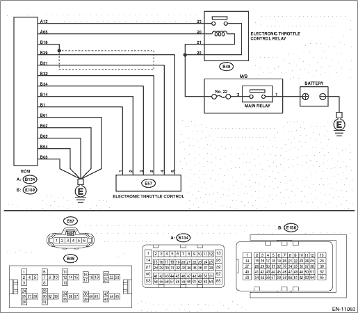
DTC DETECTING CONDITION:

Immediately at fault recognition

TROUBLE SYMPTOM:

Improper idling

Poor driving performance

Engine stalls.

CAUTION:

After servicing or replacing faulty parts, perform Clear Memory Mode Clear Memory Mode > OPERATION, and Inspection Mode Inspection Mode > PROCEDURE.

WIRING DIAGRAM:

Engine Electrical System ENGINE TYPE FB (WITHOUT PUSH BUTTON START) Engine Electrical System > WIRING DIAGRAM

Engine Electrical System ENGINE TYPE FB (WITH PUSH BUTTON START) Engine Electrical System > WIRING DIAGRAM

STEPCHECKYESNO

1.CHECK ELECTRONIC THROTTLE CONTROL RELAY.

1) Turn the ignition switch to OFF.

2) Remove the electronic throttle control relay.

3) Connect the battery to terminals No. 13 and No. 14 of electronic throttle control relay.

4) Measure the resistance between electronic throttle control relay terminals.

Terminals

No. 22 — No. 23:

Is the resistance less than 1 --

Diagnostic Procedure with Diagnostic Trouble Code (DTC) > DTC P2102 THROTTLE ACTUATOR "A" CONTROL MOTOR CIRCUIT LOW

Replace the electronic throttle control relay. Electronic Throttle Control Relay

2.CHECK POWER SUPPLY OF ELECTRONIC THROTTLE CONTROL RELAY.

Measure the voltage between electronic throttle control relay connector and chassis ground.

Connector & terminal

(B48) No. 22 (+) — Chassis ground (−):

Is the voltage 10 V or more-

Diagnostic Procedure with Diagnostic Trouble Code (DTC) > DTC P2102 THROTTLE ACTUATOR "A" CONTROL MOTOR CIRCUIT LOW

Repair the open or short to ground in the power supply circuit.

3.CHECK HARNESS BETWEEN ECM AND ELECTRONIC THROTTLE CONTROL RELAY CONNECTOR.

1) Disconnect the connector from ECM.

2) Turn the ignition switch to ON.

3) Measure the voltage between electronic throttle control relay connector and chassis ground.

Connector & terminal

(B48) No. 20 (+) — Chassis ground (−):

Is the voltage 10 V or more-

Repair the short circuit to power in the harness between ECM connector and electronic throttle control relay connector.

Diagnostic Procedure with Diagnostic Trouble Code (DTC) > DTC P2102 THROTTLE ACTUATOR "A" CONTROL MOTOR CIRCUIT LOW

4.CHECK HARNESS BETWEEN ECM AND ELECTRONIC THROTTLE CONTROL RELAY CONNECTOR.

1) Turn the ignition switch to OFF.

2) Measure the resistance between electronic throttle control relay connector and chassis ground.

Connector & terminal

(B48) No. 20 — Chassis ground:

(B48) No. 23 — Chassis ground:

Is the resistance 1 M- or more-

Diagnostic Procedure with Diagnostic Trouble Code (DTC) > DTC P2102 THROTTLE ACTUATOR "A" CONTROL MOTOR CIRCUIT LOW

Repair the short circuit to ground in harness between ECM connector and electronic throttle control relay connector.

5.CHECK HARNESS BETWEEN ECM AND ELECTRONIC THROTTLE CONTROL RELAY CONNECTOR.

Measure the resistance between ECM connector and electronic throttle control relay connector.

Connector & terminal

(B134) No. 65 — (B48) No. 20:

(B134) No. 13 — (B48) No. 23:

Is the resistance less than 1 --

Repair the poor contact of ECM connector.

Repair the open circuit in harness between ECM connector and electronic throttle control relay connector.

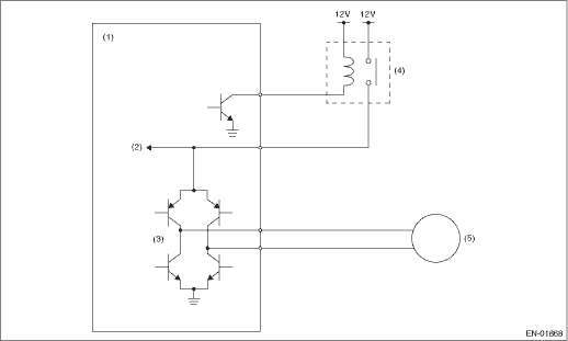
1. OUTLINE OF DIAGNOSIS

Judge as NG when the electronic throttle control power is not supplied even when ECM sets the electric control throttle relay to ON.

2. COMPONENT DESCRIPTION

(1)

Engine control module (ECM)

(3)

Drive circuit

(5)

Motor

(2)

Voltage detection circuit

(4)

Electronic throttle control relay

3. EXECUTION CONDITION

Secondary Parameters

Execution condition

Battery voltage

≥ 11 V

Electronic throttle control relay output

ON

4. GENERAL DRIVING CYCLE

Always perform the diagnosis continuously.

5. DIAGNOSTIC METHOD

If the duration of time while the following conditions are met is longer than the time indicated, judge as NG.

Judgment Value

Malfunction Criteria

Threshold Value

Motor power voltage

≤ 5 V

Time Needed for Diagnosis: 352 ms

Malfunction Indicator Light Illumination: Illuminates as soon as a malfunction occurs.

Dtc p2103 throttle actuator "a" control motor circuit high
DTC DETECTING CONDITION:Immediately at fault recognitionCAUTION:After servicing or replacing faulty parts, perform Clear Memory Mode Clear Memory Mode > OPERATION, and Inspection Mode Inspection Mod ...

Dtc p2101 throttle actuator "a" control motor circuit range/performance
DTC DETECTING CONDITION:Immediately at fault recognitionTROUBLE SYMPTOM:• Improper idling• Poor driving performance• Engine stalls.CAUTION:After servicing or replacing faulty parts, ...

Other materials:

Installation
1. Clean the mating surface of extension case and transmission case.2. Select the transfer drive gear shim. Reduction Drive Gear > ADJUSTMENT3. Select the transfer driven gear shim. Transfer Clutch > ADJUSTMENT4. Attach the selected transfer drive gear shim to extension case with vaseline.5. Attac ...

© 2017-2024 Copyright www.sulegacy.com