Subaru Legacy BN/BS (2015-2019) Service Manual: Dtc p2122 throttle/pedal position sensor/switch "d" circuit low
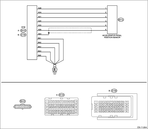
DTC DETECTING CONDITION: Immediately at fault recognition TROUBLE SYMPTOM: • Improper idling • Poor driving performance CAUTION: After servicing or replacing faulty parts, perform Clear Memory Mode Clear Memory Mode > OPERATION, and Inspection Mode Inspection Mode > PROCEDURE. WIRING DIAGRAM: • Engine Electrical System ENGINE TYPE FB (WITHOUT PUSH BUTTON START) Engine Electrical System > WIRING DIAGRAM • Engine Electrical System ENGINE TYPE FB (WITH PUSH BUTTON START) Engine Electrical System > WIRING DIAGRAM
1. OUTLINE OF DIAGNOSIS Detect the open or short circuit of accelerator pedal position sensor 1. Judge as NG if out of specification. 2. COMPONENT DESCRIPTION
3. EXECUTION CONDITION
4. GENERAL DRIVING CYCLE Always perform the diagnosis continuously. 5. DIAGNOSTIC METHOD If the duration of time while the following conditions are met is longer than the time indicated, judge as NG.
Time Needed for Diagnosis: 100 ms Malfunction Indicator Light Illumination: Illuminates as soon as a malfunction occurs. |

 Dtc p2123 throttle/pedal position sensor/switch "d" circuit high
DTC DETECTING CONDITION:Immediately at fault recognitionTROUBLE SYMPTOM:• Improper idling• Poor driving performanceCAUTION:After servicing or replacing faulty parts, perform Clear Memory M ...
 Dtc p2119 throttle actuator "a" control throttle body range/performance
NOTE:For the diagnostic procedure, refer to DTC P2101. Diagnostic Procedure with Diagnostic Trouble Code (DTC) > DTC P2101 THROTTLE ACTUATOR "A" CONTROL MOTOR CIRCUIT RANGE/PERFORMANCE1. OUTLINE OF D ...
Other materials:
Disposal of pretensioner procedure
WARNING:Make sure to follow the instructions below. Otherwise, personal injuries may occur.• Before discarding a pretensioner, always perform an activation process to prevent any false activation.• Wear protective gloves, safety goggles and earplugs during this operation. Wash your hands ...
