
Subaru Legacy BN/BS (2015-2019) Service Manual: Dtc p2402 evap system leak detection pump control circuit high
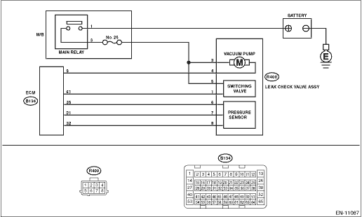
DTC DETECTING CONDITION: Immediately at fault recognition CAUTION: After servicing or replacing faulty parts, perform Clear Memory Mode Clear Memory Mode > OPERATION, and Inspection Mode Inspection Mode > PROCEDURE. WIRING DIAGRAM: • Engine Electrical System ENGINE TYPE EZ (WITHOUT PUSH BUTTON START) Engine Electrical System > WIRING DIAGRAM • Engine Electrical System ENGINE TYPE EZ (WITH PUSH BUTTON START) Engine Electrical System > WIRING DIAGRAM
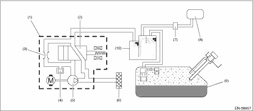
1. OUTLINE OF DIAGNOSIS Detect the open or short circuit of the ELCM vacuum pump. Judge as NG if out of specification. 2. COMPONENT DESCRIPTION
3. EXECUTION CONDITION
4. GENERAL DRIVING CYCLE Perform the diagnosis only once after the enable conditions have been established. 5. DIAGNOSTIC METHOD If the duration of time while the following conditions are met is longer than the time indicated, judge as NG.
Time Needed for Diagnosis: 2500 ms Malfunction Indicator Light Illumination: Illuminates as soon as a malfunction occurs. |
 Dtc p2404 evap system leak detection pump sense circuit range/performance
DTC DETECTING CONDITION:Detected when two consecutive driving cycles with fault occur.CAUTION:After servicing or replacing faulty parts, perform Clear Memory Mode Clear Memory Mode > OPERATION, and I ...
 Dtc p2401 evap system leak detection pump control circuit low
DTC DETECTING CONDITION:Immediately at fault recognitionCAUTION:After servicing or replacing faulty parts, perform Clear Memory Mode Clear Memory Mode > OPERATION, and Inspection Mode Inspection Mod ...
Other materials:
Inspection mode procedure
1. VDC SYSTEM1. Delete the DTC.2. Drive the vehicle at least ten minutes. (Reproduce nearly the same condition as occurred when the DTC was recorded.)NOTE:Make sure the vehicle is not dragged to one side under usual driving condition.2. ELECTRONIC PARKING BRAKE SYSTEM1. Start the engine, and operate ...
