Honda Civic manuals

Subaru Legacy BN/BS (2015-2019) Service Manual: Dtc p2530 ignition switch run position circuit

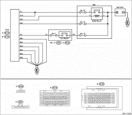
DTC DETECTING CONDITION:

Immediately at fault recognition

TROUBLE SYMPTOM:

Improper idling

CAUTION:

After servicing or replacing faulty parts, perform Clear Memory Mode Clear Memory Mode > OPERATION, and Inspection Mode Inspection Mode > PROCEDURE.

WIRING DIAGRAM:

Engine Electrical System ENGINE TYPE EZ (WITHOUT PUSH BUTTON START) Engine Electrical System > WIRING DIAGRAM

Engine Electrical System ENGINE TYPE EZ (WITH PUSH BUTTON START) Engine Electrical System > WIRING DIAGRAM

STEPCHECKYESNO

1.CHECK ECM CONNECTOR.

Check the connecting condition of ECM connector.

Is the ECM connector correctly connected-

Diagnostic Procedure with Diagnostic Trouble Code (DTC) > DTC P2530 IGNITION SWITCH RUN POSITION CIRCUIT

Connect the ECM connector correctly.

2.CHECK INPUT VOLTAGE OF ECM.

1) Turn the ignition switch to ON.

2) Connect the check board.

ST 18460AA030CHECK BOARD

3) Measure the voltage between ECM connector and engine ground while wiggling the harness between ECM connector and ignition switch connector (for models without push button start), or between ECM connector and IG relay 1 (push button start) connector (for models with push button start).

Connector & terminal

(B134) No. 2 (+) — Engine ground (−):

Is the voltage 8 V or more all the time-

Even if DTC is detected, the circuit has returned to a normal condition at this time. Reproduce the failure, and then perform the diagnosis again.

NOTE:

In this case, the following items may be the cause of fault.

Model without push button start

Open circuit or short circuit to ground in harness between ECM connector and ignition switch connector

Poor contact of ignition switch connector

Poor contact of ignition switch

Model with push button start

Open circuit or short circuit to ground in harness between ECM connector and IG relay 1 (push button start) connector

Poor contact in IG relay 1 (push button start) connector

Poor contact in IG relay 1 (push button start)

Repair the harness and connector.

NOTE:

In this case, repair the following item:

Model without push button start

Open circuit or short circuit to ground in harness between ECM connector and ignition switch connector

Poor contact of ignition switch connector

Poor contact of ignition switch

Faulty fuse (F/B No. 12)

Model with push button start

Open circuit or short circuit to ground in harness between ECM connector and IG relay 1 (push button start) connector

Poor contact in IG relay 1 (push button start) connector

Poor contact in IG relay 1 (push button start)

Faulty fuse (F/B No. 12)

1. OUTLINE OF DIAGNOSIS

Detect instantaneous open in ignition switch input circuit to ECM.

Judge as NG if out of specification.

2. COMPONENT DESCRIPTION

ECM monitors the voltage of the ignition switch input circuit. Judge as ignition switch ON when the voltage is the specified value or more.

3. EXECUTION CONDITION

Secondary Parameters

Execution condition

Battery voltage

≥ 10.9 V

Engine speed

≥ 525 rpm

4. GENERAL DRIVING CYCLE

Perform the diagnosis continuously after the enable conditions have been established.

5. DIAGNOSTIC METHOD

Judge as NG when the following conditions are established within the predetermined time.

Judgment Value

Malfunction Criteria

Threshold Value

Number of instantaneous opens in ignition switch input circuit

≥ 5 time(s)

Time Needed for Diagnosis: 5000 ms

Malfunction Indicator Light Illumination: Illuminates as soon as a malfunction occurs.

Dtc p2610 ecm/pcm engine off timer performance
DTC DETECTING CONDITION:Detected when two consecutive driving cycles with fault occur.CAUTION:After servicing or replacing faulty parts, perform Clear Memory Mode Clear Memory Mode > OPERATION, and I ...

Dtc p2420 evap system switching valve control circuit high
DTC DETECTING CONDITION:Immediately at fault recognitionCAUTION:After servicing or replacing faulty parts, perform Clear Memory Mode Clear Memory Mode > OPERATION, and Inspection Mode Inspection Mod ...

Other materials:

Inspection
Check the following items.• Check the oil pump for damage and wear.• Rotate the oil pump by hand, and check that it rotates smoothly.1. Measure the secondary pressure. Secondary Pressure (Line Pressure) Test > INSPECTION2. Remove the oil pan and oil strainer. Oil Pan and Strainer > REM ...

© 2017-2024 Copyright www.sulegacy.com