Subaru Legacy BN/BS (2015-2019) Service Manual: Electrical specification
1. STEREO CAMERA
2. ENGINE CONTROL MODULE (ECM) For details on the input/output signals for the engine control module, refer to ENGINE (DIAGNOSTICS). Engine Control Module (ECM) I/O Signal Engine Control Module (ECM) I/O Signal 3. VDC CONTROL MODULE (VDCCM) For details on the input/output signals for VDC control module, refer to VDC (DIAGNOSTICS). Control Module I/O Signal > ELECTRICAL SPECIFICATION 4. TRANSMISSION CONTROL MODULE (TCM) For details on the input/output signals for the transmission control module, refer to AUTOMATIC TRANSMISSION (DIAGNOSTICS). Transmission Control Module (TCM) I/O Signal 5. BODY INTEGRATED UNIT Refer to the BODY CONTROL SYSTEM (DIAGNOSTICS) for the I/O Signal of the body integrated unit. Control Module I/O Signal > ELECTRICAL SPECIFICATION 6. COMBINATION METER For details on the input/output signals for the combination meter, refer to COMBINATION METER (DIAGNOSTICS). Control Module I/O Signal > ELECTRICAL SPECIFICATION |
 System block diagram
Main signals used between stereo camera and relevant CM ...
 Wiring diagram
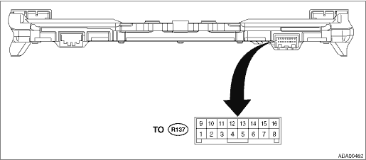
Refer to “EyeSight System” in the wiring diagram. EyeSight System ...
Other materials:
General precautions regarding SRS airbag
system
WARNING
To obtain maximum protection in
the event of an accident, the
driver and all passengers must
always wear seatbelts when in
the vehicle. The SRS airbag is
designed only to be a supplement
to the primary protection
provided by the seatbelt. It does
...
