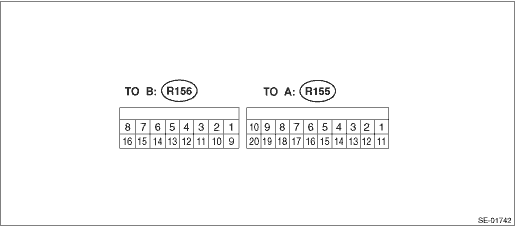
(R155) No. 1 | — | — | — |
(R155) No. 2 ←> Chassis ground | Lifter switch (down) | Switch ON | 1.5 V or less |
(R155) No. 3 ←> Chassis ground | Lifter switch (up) | Switch ON | 1.5 V or less |
(R155) No. 4 ←> Chassis ground | Tilt switch (down) | Switch ON | 1.5 V or less |
(R155) No. 5 ←> Chassis ground | Tilt switch (up) | Switch ON | 1.5 V or less |
(R155) No. 6 ←> Chassis ground | Slide switch (forward) | Switch ON | 1.5 V or less |
(R155) No. 7 ←> Chassis ground | Slide switch (rearward) | Switch ON | 1.5 V or less |
(R155) No. 8 ←> Chassis ground | Reclining switch (forward) | Switch ON | 1.5 V or less |
(R155) No. 9 ←> Chassis ground | Reclining switch (backward) | Switch ON | 1.5 V or less |
(R155) No. 10 ←> Chassis ground | Battery power supply | Always | 10 — 16 V |
(R155) No. 11 ←> Chassis ground | Ignition power supply | When ignition switch is ON | 10 — 16 V |
(R155) No. 12 | LIN communication line | Unmeasurable | — |
(R155) No. 13 ←> Chassis ground | Memory switch 1 | Switch ON | 1 V or less |
(R155) No. 14 ←> Chassis ground | Memory switch 2 | Switch ON | 1 V or less |
(R155) No. 15 ←> Chassis ground | SET switch | Switch ON | 1 V or less |
(R155) No. 16 ←> (R155) No. 20 | Reclining pulse signal | When the motor is in operation | Pulse output |
(R155) No. 17 ←> (R155) No. 20 | Tilt pulse signal | When the motor is in operation | Pulse output |
(R155) No. 18 ←> (R155) No. 20 | Lifter pulse signal | When the motor is in operation | Pulse output |
(R155) No. 19 ←> (R155) No. 20 | Slide pulse signal | When the motor is in operation | Pulse output |
(R155) No. 20 ←> Chassis ground | Pulse signal GND | Always | 1 - or less |
(R156) No. 1 ←> Chassis ground | Lifter motor up | When the motor is in operation | 9.5 — 16 V |
(R156) No. 2 ←> Chassis ground | Lifter motor down | When the motor is in operation | 9.5 — 16 V |
(R156) No. 3 ←> Chassis ground | Battery power supply | Always | 10 — 16 V |
(R156) No. 4 ←> Chassis ground | Tilt motor up | When the motor is in operation | 9.5 — 16 V |
(R156) No. 5 ←> Chassis ground | Tilt motor down | When the motor is in operation | 9.5 — 16 V |
(R156) No. 6 ←> Chassis ground | Reclining motor forward | When the motor is in operation | 9.5 — 16 V |
(R156) No. 7 ←> Chassis ground | Reclining motor backward | When the motor is in operation | 9.5 — 16 V |
(R156) No. 8 ←> Chassis ground | Battery power supply | Always | 10 — 16 V |
(R156) No. 9 ←> Chassis ground | Encoder power supply output | Always | 1 M- or more |
(R156) No. 10 | — | — | — |
(R156) No. 11 | — | — | — |
(R156) No. 12 ←> Chassis ground | GND | Always | 1 - or less |
(R156) No. 13 | — | — | — |
(R156) No. 14 ←> Chassis ground | GND | Always | 1 - or less |
(R156) No. 15 ←> Chassis ground | Slide motor rearward | When the motor is in operation | 9.5 — 16 V |
(R156) No. 16 ←> Chassis ground | Slide motor forward | When the motor is in operation | 9.5 — 16 V |
 Wiring diagram
