Honda Civic manuals

Subaru Legacy BN/BS (2015-2019) Service Manual: Electrical specification
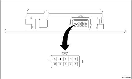
1. RADAR SENSOR

Terminal No.

Content

Measuring condition

Standard

Radar sensor LH (master)

Radar sensor RH (slave)

1 ←> Chassis ground

Private CAN H

Private CAN H

Always

1 M- or more

2 ←> Chassis ground

Master CAN H

Always

1 M- or more

3 ←> Chassis ground

4 ←> Chassis ground

Left mirror LED output

Right mirror LED output

Ignition switch OFF > ON

BSD/RCTA OFF switch OFF > ON

When indicator is ON: 2.5 — 10.5 V

When indicator is blinking: 0 ←> 2.5 — 10.5 V

When indicator is OFF: Less than 1 V

5 ←> Chassis ground

Ignition power supply

Ignition power supply

Ignition switch OFF > ON

Less than 1 V > 9 — 16 V

6 ←> Chassis ground

Private CAN L

Private CAN L

Always

1 M- or more

7 ←> Chassis ground

Master CAN L

Always

1 M- or more

8 ←> Chassis ground

BSD/RCTA OFF switch

Ignition switch ON

BSD/RCTA OFF switch OFF > ON (while pressing and holding the switch)

Less than 1 V > 9 — 16 V

9 ←> Chassis ground

10 ←> Chassis ground

GND

GND

Always

Less than 1 -

System block diagram
• BSD/RCTA system is configured by the following components.• There is a control ECM in the radar sensor main body, which performs the vehicle identification and the alert judgment control ...

Wiring diagram
Refer to “BSD/RCTA System” in the wiring diagram. Blind Spot Detection/Rear Cross Traffic Alert > WIRING DIAGRAM ...

Other materials:

SRS airbag system servicing
WARNING  When discarding an airbag module or scrapping the entire vehicle damaged by a collision, consult your SUBARU dealer.  The SRS airbag has no userserviceable parts. Do not use electrical test equipment on any circuit related to the SRS airbag ...

© 2017-2024 Copyright www.sulegacy.com