Subaru Legacy BN/BS (2015-2019) Service Manual: Inspection
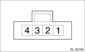
1. Measure the resistance between switch terminals. Preparation tool: Circuit tester
2. Apply battery voltage between the connector terminals to check lighting condition of illumination inside the switch.
3. Replace the memory height switch, if the inspection result is not within the standard value. |
 Removal
1. Disconnect the ground terminal from battery sensor. NOTE2. Remove the cover assembly - instrument panel LWR driver. Instrument Panel Lower Cover > REMOVAL3. Release the claws and remove the memor ...
 Installation
1. Install the memory height switch.2. Install the cover assembly - instrument panel LWR driver.3. Connect the ground terminal to battery sensor. NOTE ...
Other materials:
Dtc b27a2 passenger side external antenna open
DTC DETECTING CONDITION:When open circuit occurs in the harness between keyless access CM and passenger’s side front door outer handle antenna.TROUBLE SYMPTOM:Keyless access system does not function.CAUTION:For replacement procedure of keyless access CM, refer to the “REGISTRATION MANUAL ...
