Subaru Legacy BN/BS (2015-2019) Service Manual: Inspection
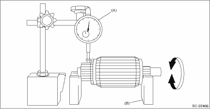
1. ARMATURE 1. Check the commutator for signs of seizure or stepped wear caused by roughness of the surface. If there is light wear, use sandpaper to repair. 2. Check for runout on the commutator. If excessive, replace the armature. Commutator runout: Standard 0.05 mm (0.0020 in) Limit 0.10 mm (0.0039 in)
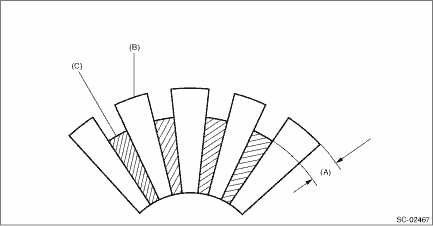
3. Check the depth of the segment mold. If it is not within the standard, replace the armature. Depth of segment mold: Standard 0.50 mm (0.020 in)
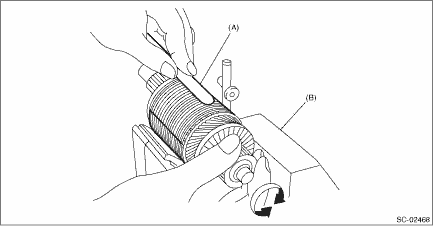
4. Place the armature on the growler tester to check for short circuits. While slowly turning the armature, support the steel sheet for the armature core. If the circuit of the armature is shorted, the steel sheet will vibrate, causing it to move towards the core. When the steel sheet has moved or vibrated, replace the armature.
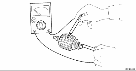
5. Use a circuit tester to touch the probe of one side to the commutator segment, and the other probe to the shaft. If there is continuity, replace the armature.
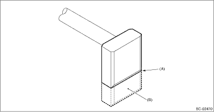
2. YOKE Make sure that the pole is set at the predetermined position. 3. OVERRUNNING CLUTCH Inspect the pinion, and if there is any wear or damage, replace the overrunning clutch. Also, check that the pinion rotates counterclockwise smoothly and does not rotate clockwise. If there is any fault, replace the overrunning clutch. CAUTION: To prevent spilling of grease, do not clean the overrunning clutch with oil. 4. BRUSH AND BRUSH HOLDER 1. Visually check the brush. If there is any abnormal wear or cracks, replace the brush. 2. Measure the length of the brush. If it exceeds service limits, replace the brush. Brush length: Standard 12.3 mm (0.484 in) Limit 7.0 mm (0.276 in)
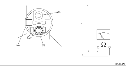
3. Check that the brush moves smoothly in the brush holder. 4. Measure the brush spring force with a spring scale. Replace the brush holder if below the service limit. Brush spring force: Standard 15.9 — 19.5 N (1.62 — 1.99 kgf, 3.57 — 4.38 lbf) (when new) Limit 2.5 N (0.25 kgf, 0.56 lbf) 5. SWITCH ASSEMBLY Using a circuit tester, check there is continuity between S terminal and M terminal, and between S terminal and ground. Also, check that there is no continuity between M terminal and B terminal.
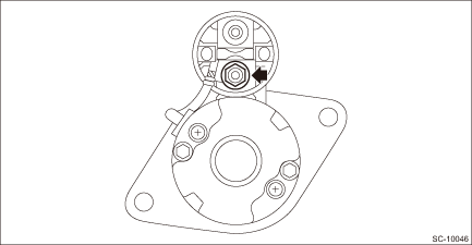
6. SWITCH ASSEMBLY OPERATION CAUTION: Perform the inspection in a short period of time. (Within 3 to 5 seconds) 1. Loosen the nut which holds the M terminal to the starter body. NOTE: This procedure is required to facilitate the harness removal from the M terminal.
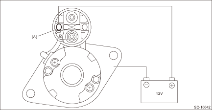
2. Connect the battery positive terminal to the switch assembly S terminal, and connect the battery negative terminal to the starter body. Then, if the pinion protrudes, it is normal. NOTE: The starter motor may rotate while the pinion protrudes. This occurs due to current that flows to the motor via pull-in coil. This is not a problem.
3. Disconnect the harness from the M terminal. Check that the pinion is being protruded at this time. CAUTION: Hold the disconnected harness so that it does not contact the terminal or wiring. 4. Disconnect the battery negative terminal from the starter body. Then, if the pinion returns to its original position, it is normal.
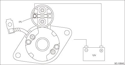
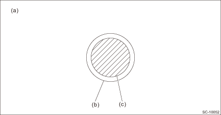
7. NO-LOAD TEST The starter should be placed through a no-load test whenever it has been overhauled. For no-load test, use the circuit shown in figure. CAUTION: • Use a thick cable due to large current flowing through the cable. • For B terminal and ground, it is recommended that the cross-section area of continuity part (shaded part) should be 20 mm 2 (0.00310 sq in) or more. For S terminal, 1.25 mm 2 (0.00194 sq in) or more.
• It is possible to use a booster cable instead of wiring. • Be careful not to burn yourself and cause a fire due to heat. • Perform the no-load test in a short period of time. (Within 3 to 5 seconds)
1. Using a vise, secure the starter. CAUTION: Be careful not to deform or damage the starter. 2. Turn the switch ON, and check that the pinion protrudes rapidly into the specified position and rotates powerfully without noise. 3. Check the current and voltage after its rotation speed stabilizes. Current/Voltage 90 A or less (approx. 11 V) 8. OTHER INSPECTIONS Check that the starter does not have deformation, cracks and any other damage. |

 Installation
1. Install the starter to the transmission.NOTE:Tighten the starter and bracket (a) together using the upper bolt securing the starter.Tightening torque:50 N·m (5.1 kgf-m, 36.9 ft-lb)2. Connect ...
 Disassembly
1. Disconnect the terminal M from the magnet switch assembly.2. Remove the magnet switch assembly from the starter housing assembly.3. Remove screws (A) of the brush holder assembly, and through bolts ...
Other materials:
Engine
Model2.5 L DOHC non-turbo3.6 L DOHC non-turboEngine typeHorizontally opposed, liquid cooled, 4-cylinder, 4-stroke gasoline engineHorizontally opposed, liquid cooled, 6-cylinder, 4-stroke gasoline engineValve arrangementDOHCBore - strokemm (in)94.0 - 90.0 (3.70 - 3.54)92.0 - 91.0 (3.62 - 3.58)Displac ...
