Subaru Legacy BN/BS (2015-2019) Service Manual: Installation
1. 16-INCH TYPE NOTE: Before installation, remove mud and foreign matter from the caliper body assembly and support - front disc brake. 1. Check each part. Front Disc Brake Assembly > INSPECTION 2. Apply a thin coat of grease to the support - front disc brake. Grease: Support - front disc brake: Molykote G-5029 or equivalent
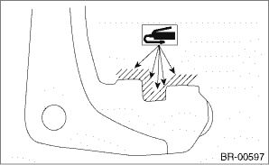
3. Install the support - front disc brake. Tightening torque: Mounting bolt: 120 N·m (12.2 kgf-m, 88.5 ft-lb) 4. Apply a thin coat of grease to the shim - disc brake front and the pad - disc brake front. • Inner side: Apply a thin coat of grease to the both sides of shim - disc brake front inner and the pad - disc brake front. Grease: Shim and pad: Molykote M77 or equivalent
• Outer side: Apply a thin coat of grease to the pad - disc brake front. Grease: Shim and pad: Molykote M77 or equivalent
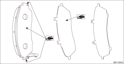
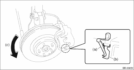
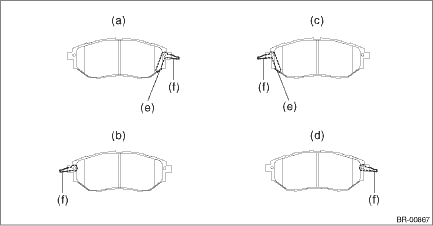
5. Install the spring - brake pad and the pad - disc brake front. NOTE: Install so that the pad indicator faces the inner side.
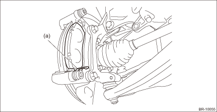
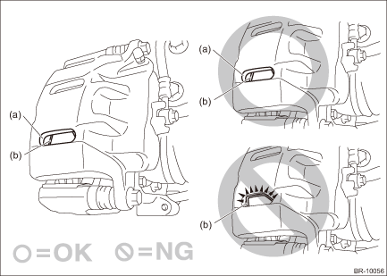
6. Install the caliper body assembly. Tightening torque: 50 N·m (5.1 kgf-m, 36.9 ft-lb) NOTE: Install so that the spring - brake pad (b) does not protrude out of the hole (a).
7. Connect the brake hose using a new brake hose gasket. Tightening torque: Union bolt: 26 N·m (2.7 kgf-m, 19.2 ft-lb) 8. Bleed air from the brake system. Air Bleeding > PROCEDURE 9. Install the front wheels. Tightening torque: 120 N·m (12.2 kgf-m, 88.5 ft-lb) 2. 17-INCH TYPE NOTE: Before installation, remove mud and foreign matter from the caliper body assembly and support - front disc brake. 1. Check each part. Front Disc Brake Assembly > INSPECTION 2. Apply a thin coat of grease to the pad clip. Grease: Pad clip: Item contained in the pad kit or equivalent
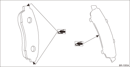
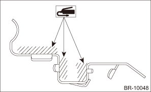
3. Install the support - front disc brake. Tightening torque: Mounting bolt: 120 N·m (12.2 kgf-m, 88.5 ft-lb) 4. Install the brake pad. CAUTION: • Be sure to install so that the pad return spring faces the input side of the direction of brake rotor rotation, as shown in the figure. • Correctly install the pad return spring to the supporting surface of the pad clip as shown in the figure. • If the pad return spring is deformed or damaged, replace the brake pad with a new part.
NOTE: Install the brake pad indicator in proper direction.
5. Install the caliper body assembly. Tightening torque: 27 N·m (2.8 kgf-m, 19.9 ft-lb) 6. Connect the brake hose using a new brake hose gasket. Tightening torque: Union bolt: 26 N·m (2.7 kgf-m, 19.2 ft-lb) 7. Bleed air from the brake system. Air Bleeding > PROCEDURE 8. Install the front wheels. Tightening torque: 120 N·m (12.2 kgf-m, 88.5 ft-lb) |
 Assembly
1. Check each part. Front Disc Brake Assembly > INSPECTION2. Clean the inside of the caliper body using brake fluid.Fluid:FMVSS No. 116, DOT3 or DOT43. Install the piston seal and the piston - disc b ...
 Inspection
1. Check the piston sliding part of caliper body and the piston for uneven wear, damage or rust.2. Check the rubber parts for damage or deterioration.3. If faulty is found in the inspection, replace t ...
Other materials:
Removal
1. MAIN SWITCH1. Disconnect the ground terminal from the battery sensor, and wait for at least 60 seconds before starting work. NOTE2. Remove the trim panel - front door. Door Trim > REMOVAL3. Remove the panel - power window main switch.CAUTION:Be careful not to damage the trim panel - front door ...
