Subaru Legacy BN/BS (2015-2019) Service Manual: Installation
CAUTION: • Refer to “CAUTION” of “General Description” before handling the airbag system components. General Description > CAUTION • After installing the panel center assembly, check that the air vent grille of the panel center assembly is inserted correctly into the air vent duct. • When installing the cover - instrument panel side (a), make sure that the body side weather strip - flange front does not come inside the panel COMPL - instrument (b).
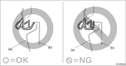
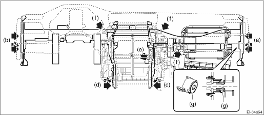
• When reusing the tether clip on the upper part of the trim panel - front pillar UPR, check that there is no damage to the tether clip. If the tether clip is damaged, always replace it with a new tether clip. If the tether clip is damaged, its holding force is reduced and the trim panel - front pillar UPR may come off. • Do not reuse the tether clip removed from the upper part of the trim panel - front pillar UPR. Always replace with a new part. 1. Attach components until the instrument panel assembly is formed, in the reverse order of removal. NOTE: Method of installing insulator • Adhesive Use polyurethane adhesive. When assembling the instrument panel assembly, wait until the adhesive has evaporated to prevent filling of the smell in the compartment. • Double-sided tape Use commercial double-sided tape. (Use strong double-sided adhesive tape.) 2. Install the beam COMPL - steering. (1) Place the beam COMPL - steering on the vehicle, and check that the pins on both sides are inserted securely and the harness is routed properly. Connect each connector. (2) Secure the beam COMPL - steering to the heater and cooling unit assembly. (e), (f) Tightening torque: 7.5 N·m (0.8 kgf-m, 5.5 ft-lb) (3) Temporarily tighten the bolts (c) and (d) of the beam COMPL - steering. (4) Tighten the adjuster portion (g) of the adjuster - clip space. (Only RH side of the beam COMPL - steering) Preparation tool: Hexagon wrench: 8 mm (0.31 in) NOTE: When the TORX® bolt is tightened after setting the adjuster portion (g) of the adjuster - clip space to the free position, the adjuster is secured at the position where there is no gap to the body, and then the TORX® bolt is tightened. Tightening torque: Adjuster - clip space: 0.8 — 4 N·m (0.08 — 0.4 kgf-m, 0.6 — 3 ft-lb)
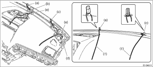
(5) Tighten the beam COMPL - steering in the order from (a) to (d) to the specified torque. Tightening torque: 25 N·m (2.5 kgf-m, 18.4 ft-lb) 3. Install the instrument panel assembly. CAUTION: Be careful not to allow the harness to be caught. (1) Tie a string to the connector of sunload sensor - auto light, and then pull the string so that each connector is placed at the specified position. (2) Secure the harness clamp.
(3) Install the sunload sensor and the sensor - auto light. (4) Insert the matching pins on the body side (three locations - one in the center and the remaining two on both sides) into the instrument panel assembly and the beam COMPL - steering. (5) Install the duct - center vent front, and secure the instrument panel assembly to the beam COMPL - steering with screws. 4. Insert the matching pins on the body side (three locations - one in the center and the remaining two on both sides) into the instrument panel assembly and the beam COMPL - steering. 5. Install the telematics sub antenna.
6. Install the passenger’s airbag module. Tightening torque: 7.5 N·m (0.8 kgf-m, 5.5 ft-lb) 7. Install the column assembly - steering. Tightening torque: Column assembly - steering: General Description > COMPONENT 8. Install the cover side sill - front and the front cover - side sill on the left and right sides. 9. Install the speaker assembly. 10. Install the keyless access CM. Tightening torque: 7.5 N·m (0.8 kgf-m, 5.5 ft-lb) 11. Install the combination meter assembly. Tightening torque: 7 N·m (0.7 kgf-m, 5.2 ft-lb) 12. Install the visor assembly - lower. 13. Install the audio assembly or navigation assembly. 14. Install the heater control assembly. 15. Install the center grille assembly. 16. Install the glove box assembly. 17. Install the trim panel - front pillar UPR on the RH and LH sides. 18. Install the grille speaker side on the RH and LH sides. 19. Install the panel - knee guard. Tightening torque: 7 N·m (0.7 kgf-m, 5.2 ft-lb) 20. Install the cover assembly - instrument panel LWR driver. 21. Install the body side weather strip - flange front. 22. Install the ornament panel - console, cover assembly - front, console box assembly and the panel center LWR. Tightening torque: Console box assembly: 6.5 N·m (0.6 kgf-m, 4.8 ft-lb) 23. Install the front seat assembly to the body. Front Seat > INSTALLATION 24. Connect the ground terminal to battery sensor. NOTE |
 Removal
CAUTION:• Refer to “CAUTION” of “General Description” before handling the airbag system components. General Description > CAUTION• Be careful not to damage the air ...

Other materials:
Removal
1. Remove the manual transmission assembly from the vehicle. Manual Transmission Assembly > REMOVAL2. Remove the transfer case together with the extension case assembly. Transfer Case and Extension Case Assembly > REMOVAL3. Remove the transmission case. Transmission Case > REMOVAL4. Remove the dr ...
