Subaru Legacy BN/BS (2015-2019) Service Manual: Installation
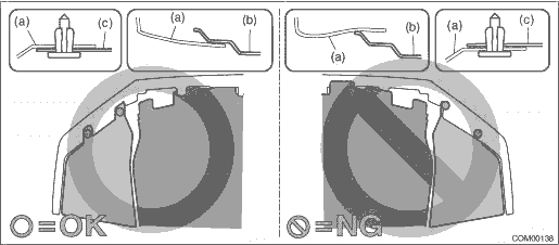
CAUTION: • Install the bumper face - front so that the front end of the under cover (b) comes inside the bumper face - front (a), and the front end of the mud guard (c) comes outside the bumper face - front (a).
• Before installing the bumper face, match the claws on the bracket - front bumper with the engaging position of flange section on the bumper face side. If the engaging position is not correct, the flange section may be broken or the clearance between fender panel and bumper face may not be uniform. 1. Install the light assembly - head. Tightening torque: 7.5 N·m (0.8 kgf-m, 5.5 ft-lb) 2. Install the bracket - front bumper corner. Tightening torque: 7.5 N·m (0.8 kgf-m, 5.5 ft-lb) 3. Install the cover - front fender UPR. 4. Install the bumper face - front. Front Bumper > INSTALLATION 5. Connect the ground terminal to battery sensor. NOTE 6. Adjust the headlight beam and fog light beam. • Adjust the headlight beam. Headlight Assembly > ADJUSTMENT • Adjust the fog light beam. (Model with fog light) Front Fog Light Assembly > ADJUSTMENT |
 Adjustment
1. HEADLIGHT BEAM ADJUSTMENTCAUTION:• Turn off the light before adjusting the headlight beam level. If it is necessary to inspect the beam level, do not keep the light on for two minutes or more ...
 Disassembly
CAUTION:Use a dry clean cloth so that no grease or water adheres to the glass portion of the bulb.1. HIGH BEAM BULB1. Disconnect the connector.2. Rotate in the direction of arrow shown in the figure t ...
Other materials:
Inspection
1. Check that the knock sensor has no deformation, cracks or other damages.2. Measure the resistance between knock sensor terminals.Terminal No.Standard1 and 2560±28 k- ...
