Subaru Legacy BN/BS (2015-2019) Service Manual: Installation
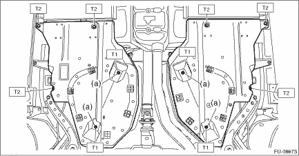
1. PARKING BRAKE HARNESS 1. Install the electronic parking brake harness. Tightening torque: Harness clamp: 18 N·m (1.8 kgf-m, 13.3 ft-lb) 2. Install the fuel tank protector. NOTE: Use a new self-locking nut (a). Tightening torque: T1: 9 N·m (0.9 kgf-m, 6.6 ft-lb)
3. Connect the ground terminal to battery sensor. NOTE 4. Install the rear wheels. Tightening torque: 120 N·m (12.2 kgf-m, 88.5 ft-lb) 2. PARKING BRAKE ACTUATOR CAUTION: • Do not remove the parking brake actuator assembly except when there are system malfunctions (such as emergency release of parking brake or abnormal actuator) or when the caliper is replaced. When the parking brake actuator assembly is reused, always replace the O-ring with a new part contained in the caliper body assembly. • Do not reuse the parking brake actuator assembly when the emergency release of parking brake was performed or when the actuator has a malfunction. Always replace with a new parking brake actuator assembly. 1. Install the parking brake actuator assembly. Tightening torque: 8 N·m (0.8 kgf-m, 5.9 ft-lb) 2. Connect the ground terminal to battery sensor. NOTE 3. Using the Subaru Select Monitor, exit the brake maintenance mode according to the display screen. Parking Brake System > OPERATION NOTE: For detailed operation procedures, refer to “Application help”. 4. After the operation is completed, apply and release the parking brake five times and ensure that the brake operates normally. 5. Install the rear wheels. Tightening torque: 120 N·m (12.2 kgf-m, 88.5 ft-lb) |
 Removal
1. PARKING BRAKE HARNESS1. Disconnect the ground terminal from battery sensor. NOTE2. Lift up the vehicle, and then remove the rear wheels.3. Remove the bolt and nuts and remove the fuel tank protect ...

Other materials:
Installation
1. Install the sensor assembly - headlight beam leveler.Tightening torque:7.5 N·m (0.8 kgf-m, 5.5 ft-lb)2. Install the rear wheels.Tightening torque:120 N·m (12.2 kgf-m, 88.5 ft-lb)3. Lower the vehicle.4. Connect the ground terminal to battery sensor. NOTE5. Perform reinitialization o ...
