Subaru Legacy BN/BS (2015-2019) Service Manual: Installation
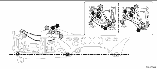
CAUTION: • For parts which are not reusable, always use new parts. • Always tighten the bushing when the arm is positioned in the state where the vehicle is at curb weight and the wheels are in full contact with the ground. 1. Before installation, inspect the following items and replace any faulty part with a new one. • Visually check the upper arm assembly for damage and deformation. • Visually check the bushing for abnormal cracks, fatigue or damage. • Visually check the dust cover on the ball joint for abnormal cracks, fatigue or damage. 2. Install the upper arm assembly. (1) Make the installation sections of the rear lateral link assembly (the bolt on the housing assembly - rear axle side and the bolt on the rear sub frame assembly side) horizontal. (2) Install the upper arm assembly to the rear sub frame assembly.
Tightening torque: Upper arm assembly — rear sub frame assembly: 80 N·m (8.2 kgf-m, 59.0 ft-lb) 3. Connect the upper arm assembly and the housing assembly - rear axle. Tightening torque: Upper arm assembly — housing assembly - rear axle: 80 N·m (8.2 kgf-m, 59.0 ft-lb) 4. Install the rear sub frame assembly. Rear Sub Frame > INSTALLATION 5. Install the rear wheels and lower the vehicle. Tightening torque: 120 N·m (12.2 kgf-m, 88.5 ft-lb) 6. Inspect the wheel alignment and adjust if necessary. • Inspection: Wheel Alignment > INSPECTION • Adjustment: Wheel Alignment > ADJUSTMENT CAUTION: When the wheel alignment has been adjusted, perform the following adjustment. – Lane keep assist learning value clear (model with EyeSight): Clear Active Lane Keep System Learning Value > OPERATION – “VSC(VDC) Centering Mode”: VDC Control Module and Hydraulic Control Unit (VDCCM&H/U) > ADJUSTMENT 7. Connect the ground terminal to battery sensor. NOTE 8. Perform reinitialization of the auto headlight beam leveler system. (Model with auto headlight beam leveler) Auto Headlight Beam Leveler System > PROCEDURE |
 Removal
1. Disconnect the ground terminal from battery sensor. NOTE2. Lift up the vehicle, and then remove the rear wheels.3. Remove the rear sub frame assembly. Rear Sub Frame > REMOVAL4. Remove the bolts, ...
 Seat belt system
...
Other materials:
Preparation tool
1. SPECIAL TOOLILLUSTRATIONTOOL NUMBERDESCRIPTIONREMARKS — (Newly adopted tool)SUBARU SELECT MONITOR 4Used for setting of each function and troubleshooting for electrical system.NOTE:For detailed operation procedures of Subaru Select Monitor 4, refer to “Application help”.2. GENERAL TO ...
