Subaru Legacy BN/BS (2015-2019) Service Manual: Procedure
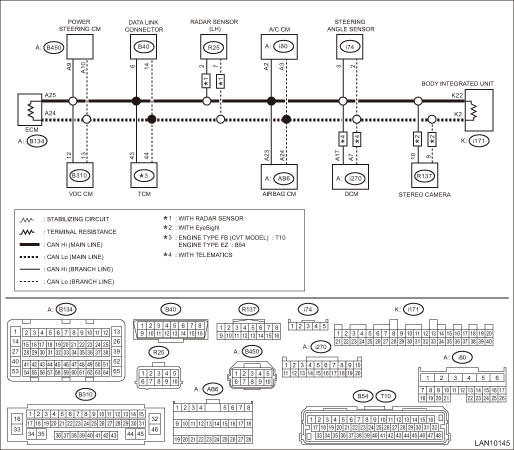
1. MAIN-CAN NOTE: • When measuring the resistance of CAN communication circuit, measure it in sleep status. To enter sleep status – With ignition switch OFF and key or switch operation stopped, keep the doors, trunk, and rear gate all closed for one minute or more. – On models with keyless access function, keep the access key 2 m or more away from the vehicle. • When the bus line is measured, combined resistance of the end resistance (120 -) in ECM and the end resistance (120 -) in body integrated unit can be measured. The combined resistance is supposed to be approximately 53 — 61 - with the stabilizing circuit included. If the measured resistance value becomes 52 - or less, main wiring harness or related lines may be shorted. Or, the combined resistance may have changed because of a resistance other than the end resistance created on the circuit. If the measured value is 62 - or more, there may be a malfunction such as open circuit in one of the end resistances, in the stabilizing circuit, or in the main wiring harness. Also, even when the resistance value falls within approx. 53 — 61 -, related lines may be open if an error of communication for initializing or a CAN system U-code has occurred. (The resistance cannot be between approx. 53 — 61 - if the main wiring harness is open.) WIRING DIAGRAM: • For the coupling connector, refer to “WIRING SYSTEM”. • CAN communication system CAN Communication System > WIRING DIAGRAM
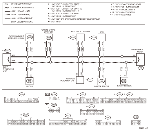
2. BODY-CAN NOTE: • When measuring the resistance of CAN communication circuit, measure it in sleep status. To enter sleep status – With ignition switch OFF and key or switch operation stopped, keep the doors, trunk, and rear gate all closed for one minute or more. – On models with keyless access function, keep the access key 2 m or more away from the vehicle. • When the bus line is measured, combined resistance of the end resistance (120 -) in body integrated unit and the end resistance (120 -) in combination meter can be measured. The combined resistance is supposed to be approximately 53 — 61 - with the stabilizing circuit included. If the measured resistance value becomes 52 - or less, main wiring harness or related lines may be shorted. Or, the combined resistance may have changed because of a resistance other than the end resistance created on the circuit. If the measured value is 62 - or more, there may be a malfunction such as open circuit in one of the end resistances, in the stabilizing circuit, or in the main wiring harness. Also, even when the resistance value falls within approx. 53 — 61 -, related lines may be open if an error of communication for initializing or a CAN system U-code has occurred. (The resistance cannot be between approx. 53 — 61 - if the main wiring harness is open.) WIRING DIAGRAM: • For the coupling connector, refer to “WIRING SYSTEM”. • CAN communication system CAN Communication System > WIRING DIAGRAM
|

 List
List
Resistance value between CAN Hi and LoContents of inspectionRemarksGround short inspection CAN Communication Circuit Check > INSPECTIONShorted to ground in the communication circuit or control module. ...
Other materials:
Adjustment
CAUTION:When the wheel alignment has been adjusted, perform the following adjustment.– Lane keep assist learning value clear (model with EyeSight): Clear Active Lane Keep System Learning Value > OPERATION– VDC sensor midpoint setting mode: VDC Control Module and Hydraulic Control Unit (VDCCM ...
