Subaru Legacy BN/BS (2015-2019) Service Manual: Removal
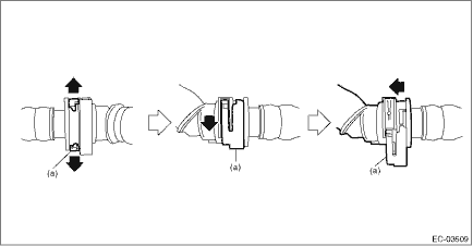
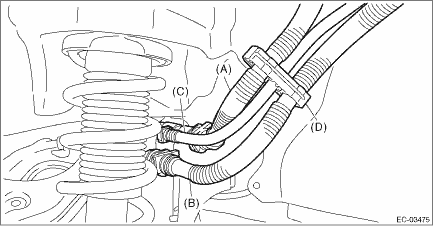
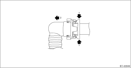
1. Disconnect the ground terminal from battery sensor. NOTE 2. Remove the rear wheel LH. Tire and Wheel > REMOVAL 3. Lift up the vehicle. 4. Remove the rear mud guard LH. Mud Guard > REMOVAL 5. Disconnect the quick connectors of the vent tube (A), canister drain tube (B) and purge tube (C), and remove the tubes from tube clamp (D). NOTE: Disconnect the quick connector as shown in the figure. • Vent tube (A) and canister drain tube (B) (Slider color is red or green.)
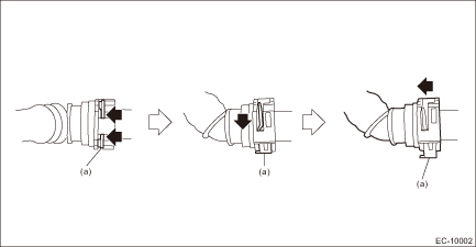
• Vent tube (A) and canister drain tube (B) (Slider color is white.)
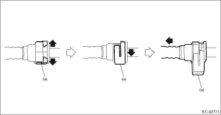
• Purge tube (C)
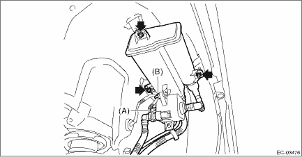
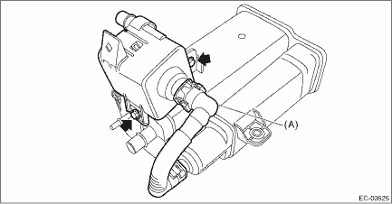
6. Disconnect the connector (A) from the canister and remove the harness clip (B). 7. Remove the canister.
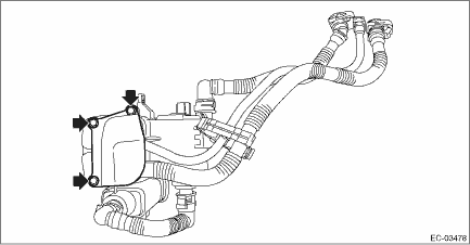
8. Remove the canister protector.
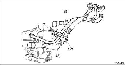
9. Disconnect the vent tube (A), canister drain tube (B) and purge tube (C). NOTE: Disconnect the quick connector as shown in the figure. • Vent tube (A) and canister drain tube (B) (Slider color is red or green.)
• Vent tube (A) and canister drain tube (B) (Slider color is white.)
• Purge tube (C)
10. Remove the hose clamp (D).
11. Disconnect the drain tube (A). NOTE: Disconnect the quick connector as shown in the figure.
12. Remove the leak check valve assembly from the canister.
|
 Canister
...
 Inspection
1. Check that the canister has no deformation, cracks or other damages.2. Check that the tube has no cracks, damage or loose part. ...
Other materials:
Dtc p0141 o2 sensor heater circuit bank 1 sensor 2
Refer to DTC P0037 for diagnostic procedure. Diagnostic Procedure with Diagnostic Trouble Code (DTC) > DTC P0037 A/F / O2 HEATER CONTROL CIRCUIT LOW BANK 1 SENSOR 21. OUTLINE OF DIAGNOSISDetect malfunction of the rear oxygen sensor heater.Judge as NG if it is determined that the rear oxygen sensor ...
