Subaru Legacy BN/BS (2015-2019) Service Manual: Adjustment
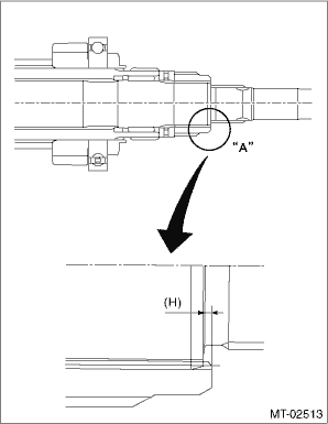
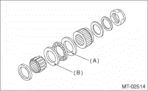
1. THRUST BEARING PRELOAD 1. Select a suitable adjusting washer No. 1 so that dimension (H) will be zero in a visual check. Position the washer (20 - 31 - 4) and lock washer (20 - 31 - 2.3) and attach the lock nut (20 - 11).
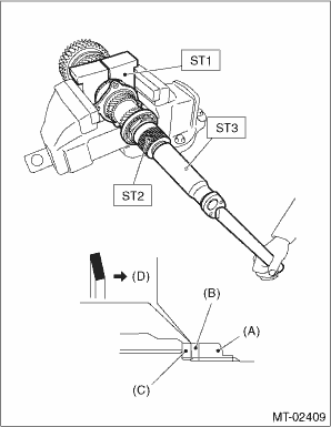
2. Install the lock nut with ST1, ST2 and ST3. NOTE: • Use new lock nuts and lock washers. • Install the lock washer in the correct direction. Tightening torque: 126 N·m (12.8 kgf-m, 92.9 ft-lb)
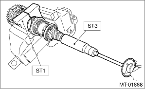
3. After removing the ST2 used in step 2), measure the starting torque using torque driver. Starting torque: 0.3 — 0.8 N·m (0.03 — 0.08 kgf-m, 0.2 — 0.6 ft-lb)
4. If the starting torque is not within the specified limit, select new adjusting washer No. 1 and recheck starting torque.
5. If the specified starting torque cannot be obtained by the selection of adjusting washer No. 1, select adjusting washer No. 2 from the list below. Repeat steps 1) through 4) to adjust starting torque.
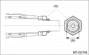
6. Recheck that the starting torque is within the specified range, and crimp the lock nut at two locations so that the dimension (B) becomes 20.1 mm (0.79 in) or less. CAUTION: When crimping the lock nut, be careful not to crack it.
| |||||||||||||||||||||||||||||||||||||||||||||||||||||||||||||||||||
 Removal
1. Remove the manual transmission assembly from the vehicle. Manual Transmission Assembly > REMOVAL2. Remove the transfer case together with the extension case assembly. Transfer Case and Extension ...
 Installation
1. Remove the front differential assembly.2. Hypoid gear set match mark/No.: The number (A) on top of the drive pinion, and the number on the hypoid driven gear are set numbers for the two gears. Use ...
Other materials:
Assembly
1. Install each cover to the front exhaust pipe.Tightening torque:13 N·m (1.3 kgf-m, 9.6 ft-lb)2. Install the front oxygen (A/F) sensor and rear oxygen sensor. Front Oxygen (A/F) Sensor > INSTALLATION Rear Oxygen Sensor > INSTALLATION3. Install the front exhaust pipe (RH) to the front exhau ...
